- Catalogs
- Gneuß Kunststofftechnik GmbH
- Operating Instructions Melt pressure transducer with switching output
Operating Instructions Melt pressure transducer with switching output
1 /16Pages

Operating Instructions Melt pressure transducer with switching output
1 /16Pages
Catalog excerpts

Measuring equipment for extruders Melt Pressure Transducer DAIL Operating Instructions Melt pressure transducer with switching output DAIL Certified to ISO 9001:2008 Please read this instruction manual carefully before installing the transducer. Gneuss Kunststofftechnik GmbH, Moenichhusen 42, 32549 Bad Oeynhausen, Germany, mail: [email protected], web: www.gneuss.com Version 2.5
Open the catalog to page 1
Measuring equipment for extruders Melt Pressure Transducer DAIL Contents: 1. Introduction 2. Operating range and field of application 3. Danger areas 4. Waste disposal 5. Transport and storage 6. Cleaning of the sensors 7. Installing / Uninstalling 8. Switching output for pressure monitoring 9. Connecting and commissioning of the DAIL 10. Technical data 11. Dimensions Gneuss Kunststofftechnik GmbH, Moenichhusen 42, 32549 Bad Oeynhausen, Germany, mail: [email protected], web: www.gneuss.com Version 2.5
Open the catalog to page 2
Measuring equipment for extruders Melt Pressure Transducer DAIL 1. Introduction: Melt pressure transducers are precise measuring probes which obtain their measuring accuracy and long life span only if they are properly handled. These operating instructions should be studied carefully before installing the sensor, thus ensuring a trouble-free operation. Nevertheless, should you encounter any difficulties, please feel free to contact our technicians or our representatives, who will be pleased to be of assistance. 2. Operating range and field of application: Gneuss melt pressure transducers with...
Open the catalog to page 3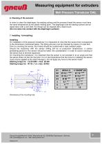
Measuring equipment for extruders Melt Pressure Transducer DAIL 6. Cleaning of the sensors: In order to clean the diaphragm, the sealing surface and the process thread the sensor must have the same temperature as the plastic melting point. The diaphragm and the sealing surface can be wiped down with a soft cloth, the thread can be cleaned with a steel brush. (Do not come into contact with the diaphragm surface!) 7. Installing / Uninstalling: Installing On installation of the pressure transducer it is imperative to note that the sensor bore corresponds to the dimensions mentioned below. The fitting...
Open the catalog to page 4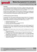
Measuring equipment for extruders Melt Pressure Transducer DAIL Uninstalling The uninstalling of the pressure transducer has to be done in a heated up condition (plastic melting point). On removal of the sensor, please take note that the diaphragm is not brought into contact with surrounding parts. It is of vital importance that the force for uninstalling the sensor must only be applied at the shaft (hexagon). Do not apply any force to the sensor head! The most common cause of failure of this kind of pressure transducers is the damage of the diaphragm during installing/uninstalling of the transducer....
Open the catalog to page 5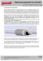
Measuring equipment for extruders Melt Pressure Transducer DAIL 9. Connections and commissioning: After the pressure transducer has been installed into the line, as described in section 7, the electrical connections have to be applied according to the connections described hereafter. Gneuss pressure transducers are equipped with high quality and robust plug connections. The connecting wire should be soldered with great care as transmission errors of signals can otherwise occur. We recommend using Gneuss prefabricated connecting wires which are available ex-stock. Pressure sensors of the type...
Open the catalog to page 6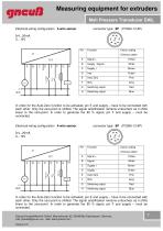
Measuring equipment for extruders Melt Pressure Transducer DAIL Electrical wiring configuration 3-wire sensor Colour coding (Gneuss cable) Supply / Signal - Auto Zero Switching output Switching output In order for the Auto-Zero function to be activated, pin E and supply – have to be connected with each other. Only the zero-point is shifted. The signal amplification remains untouched, as it shifts linear to the zero-point. In order to generate the 80 % signal, pin F and supply – must be connected. Electrical wiring configuration 4-wire sensor Colour coding (Gneuss cable) Auto Zero Switching output...
Open the catalog to page 7
Measuring equipment for extruders Melt Pressure Transducer DAIL Electrical wiring configuration 3-wire sensor Colour coding (Gneuss cable) Switching output Supply / Signal - Switching output Auto Zero - Blue Yellow In order for the Auto-Zero function to be activated, pins 5 and 8 have to be connected with each other. Only the zero-point is shifted. The signal amplification remains untouched, as it shifts linear to the zero-point. Electrical wiring configuration 3-wire sensor Colour coding (Gneuss cable) Supply / Signal - Auto Zero Switching output Switching output In order for the Auto-Zero function...
Open the catalog to page 8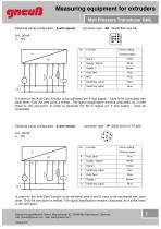
Measuring equipment for extruders Melt Pressure Transducer DAIL Electrical wiring configuration 3-wire sensor connector type: 8H (HARTING size 3A) Colour coding (Gneuss cable) Supply / Signal - Auto Zero Switching output Switching output In order for the Auto-Zero function to be activated, pin 4 and supply – have to be connected with each other. Only the zero-point is shifted. The signal amplification remains untouched, as it shifts linear to the zero-point. In order to generate the 80 % signal, pin 5 and supply – must be connected. Electrical wiring configuration 3-wire sensor Colour coding...
Open the catalog to page 9
Measuring equipment for extruders Melt Pressure Transducer DAIL Electrical wiring configuration 3-wire sensor Colour coding (Gneuss cable) Supply / Signal - Switching output Auto Zero Switching output In order for the Auto-Zero function to be activated, pin E and supply - have to be connected with each other. Only the zero-point is shifted. The signal amplification remains untouched, as it shifts linear to the zero-point. In order to generate the 80 % signal, pin A and supply – must be connected. Electrical wiring configuration 3-wire sensor Colour coding (Gneuss cable) Auto Zero Supply/Signal/Auto...
Open the catalog to page 10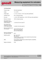
Measuring equipment for extruders Melt Pressure Transducer DAIL 10.Technical Data: Pressure range: Output signal: Calibration point: Accuracy: Maximum overload: Zero deviation with temperature variations at the membrane: ± 0.02 bar from final value/°C Zero deviation with temperature variations at the measuring head: ± 0.003 % from final value/°C Maximum temperature at the membrane: Maximum temperature at the measuring head: 300°C with NTX-filling (W) 400°C with Hg-filling (M) 500°C with NaK-filling (N) Switching output: Max. 48 V AC/DC Max. 500 mA Current limitation by means of semi-conductor...
Open the catalog to page 11All Gneuß Kunststofftechnik GmbH catalogs and technical brochures


- Valve
- Temperature probe
- Regulating valve
- Resistance temperature sensor
- Extrusion line
- Pt100 temperature transducer
- Thermocouple temperature transducer
- Thermoplastic extrusion line
- Membrane pressure sensor
- Analog pressure sensor
- RTD temperature sensor
- Recycling plant
- Threaded temperature sensor
- Analog temperature sensor
- Precision temperature transducer
- Analog pressure transducer
- Viscosity measurement device