

PRECISION BELT DRIVEN SPINDLES

PRECISION BELT DRIVEN SPINDLES
Technical Specifications and Dimensions
The document details dimensional data and maximum speed ratings for spindle interface designations including TSA, TSI, TSP, and TSAV series. Each interface type (A, I, D, V) is defined with precise measurements in millimeters for diameters, lengths, thread sizes, and other critical parameters. Maximum rotational speeds are specified for steel and hybrid bearing types, indicating performance limits per spindle variant.
Interface Types and Taper Specifications
All spindle interfaces share a nominal taper ratio of 1:7.5, corresponding to an included angle of approximately 3°49' to 3°50' per GMN precision standards. This uniform taper ensures compatibility and precision in tool mounting across all spindle types.
Spindle Interface Flange and Grinding Wheel Data
Flange styles and dimensions (parameters P, Q, L, E, F, G) are provided to support mounting and balancing of grinding wheels. Maximum permissible grinding wheel speeds vary by spindle size and interface type, ensuring safe operation.
Balancing and Vibration Monitoring Components
Information on balancing screws, weights, vibration sensors, and cabling is included to maintain spindle balance and monitor operational vibrations, critical for precision and spindle longevity.
Performance Parameters: Speed Limits and Stiffness
Speed limits for sliding seals in TSAV spindles decrease with increasing spindle size. Axial and radial stiffness values (in N/µm) and load capacities (in Newtons) are provided, reflecting the mechanical robustness of each spindle type.
Additional Technical Data
Tables include quill diameters and lengths, spindle nose interface dimensions, and surface speeds at maximum spindle speeds. Cutting speed is calculated by vc = (E · π · n) / (60 · 1000), where E is wheel diameter (mm) and n is spindle speed (rpm).
Summary of Critical Information
- Dimensional accuracy: Consistent taper angle of ~3°49' to 3°50' across all spindle interfaces.
- Speed limitations: Maximum rpm varies by spindle size and bearing type; hybrid bearings allow higher speeds.
- Load and stiffness: Quantified axial and radial stiffness and load capacities support design and application decisions.
- Balancing and vibration control: Detailed balancing components and vibration sensors ensure operational stability.
- Flange and grinding wheel compatibility: Flange dimensions and balancing features are matched to grinding wheel sizes and speeds.
This data supports precise spindle selection, tool mounting, and operational safety in high-speed grinding applications.
Spindle Load Capacities and Stiffness Specifications
1. Radial and Axial Load Capacities
- TSA models (20 to 100) specify radial load capacities across speeds from 10 to 100,000 rpm.
- TSI and TSP models (sizes 40 to 100) provide axial load capacities differentiated by direction A and B.
- TSAV series (sizes 40 to 200) show axial and radial load capacities at the spindle nose, with axial loads from 300 N (TSAV 40) to 6000 N (TSAV 200).
2. Stiffness Parameters
- Axial and radial stiffness values increase with spindle size, e.g., TSI/TSP 40: axial 32 N/µm, radial 36 N/µm; TSAV 200: axial 345 N/µm, radial 342 N/µm.
3. Directional Load and Stiffness Considerations
- Axial load capacity and stiffness are equal in directions A and B for some models.
- Radial stiffness and load relate either to taper center or spindle nose depending on spindle type.
4. Operating Speed and Vibration Limits
- Maximum spindle and critical speeds are indicated, distinguishing between unloaded spindles and those with oversized tools.
- Permissible residual unbalance values range from 0.001 to 0.01 g·mm depending on operating speed.
- Vibration measurement distances are standardized at five times taper diameter, capped at 100 mm (3.937 inches).
5. Measurement and Quality Control
- Standardized measurement distances ensure consistent vibration and unbalance quality assessments.
- Formulas and inequalities define permissible residual unbalance thresholds.
Summary Table of Critical Parameters
| Spindle Model | Axial Stiffness (N/µm) | Radial Stiffness (N/µm) | Axial Load Capacity (N) | Radial Load Capacity (N) |
|---|---|---|---|---|
| TSI/TSP 40 | 32 | 36 | 150 | 150 |
| TSI/TSP 100 | 78 | 170 | 540 | 540 |
| TSAV 40 | 56 | 29 | 300 | 300 |
| TSAV 200 | 345 | 342 | 6000 | 6000 |
Note: Load capacities and stiffness increase with spindle size and series.
Best Practices and Recommendations
- Operate spindles within specified maximum speeds to avoid resonance and excessive vibration.
- Maintain residual unbalance within permissible limits to ensure spindle longevity and precision.
- Use standardized measurement distances for vibration and unbalance to guarantee consistent quality control.
Catalog excerpts
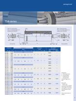
Taper 1:7.5 nominal value (3°xx' xx'') included angle acc. to GMN precision standards Tool interface Pulley interface Taper 1:7.5 nominal value (3°xx' xx'') included
Open the catalog to page 7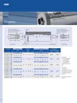
Taper 1:7.5 nominal value (3°xx' xx'') included angle acc. to GMN precision standards Taper 1:7.5 nominal value (3°xx' xx'') included angle acc. to GMN precision standards Tool interface Pulley interface
Open the catalog to page 8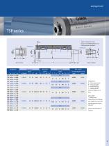
Taper 1:7.5 nominal value (3°xx' xx'') included angle acc. to GMN precision standards Tool interface Pulley interface
Open the catalog to page 9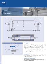
Taper 1:7.5 nominal value (3°xx' xx'') included angle acc. to GMN precision standards Taper 1:7.5 nominal value (3°xx' xx'') included angle acc. to GMN precision standards Tool interface Pulley interface Solid preloaded Bearing prload TSAV TSEV Spring preloaded TSA TSI TSP Speed
Open the catalog to page 10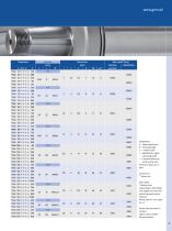
TSAV 40 ¾ ¾ ¾ x 200 TSAV 40 ¾ ¾ ¾ x 250 TSAV 40 ¾ ¾ ¾ x TSAV 60 ¾ ¾ ¾ x 200 TSAV 60 ¾ ¾ ¾ x 250 TSAV 60 ¾ ¾ ¾ x TSAV 120 ¾ ¾ ¾ x 400 TSAV 120 ¾ ¾ ¾ x 500 TSAV 120 ¾ ¾ ¾ x 630 TSAV 140 ¾ ¾ ¾ x 500 TSAV 140 ¾ ¾ ¾ x 630 TSAV 140 ¾ ¾ ¾ x 800 TSAV 160 ¾ ¾ ¾ x 400 TSAV 160 ¾ ¾ ¾ x 500 TSAV 160 ¾ ¾ ¾ x 630
Open the catalog to page 11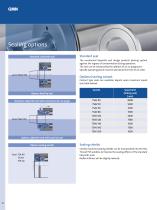
Speed limit (Sliding seal) [rpm]
Open the catalog to page 12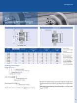
Balancing screws Flange style Flange dimensions Grinding wheel
Open the catalog to page 15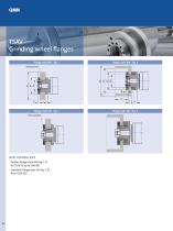
Balancing screws Balancing weights
Open the catalog to page 16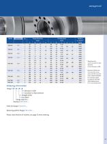
Flange dimensions Grinding wheel
Open the catalog to page 17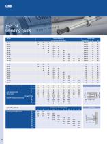
at maximum spindle speed Wheel mount see page 21, fig. Close-fit hole attachment [mm] Quill stiffness [N/µm] Grinding quill length H [mm] Grinding quill diameter K [mm] 5
Open the catalog to page 20
Spindle nose interface D 28/43 Spindle nose interface D 16/33 Spindle nose interface D 14/23 Spindle nose interface Spindle nose interface D 08/
Open the catalog to page 22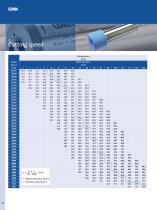
Cutting speed vc [m/s] Spindle vc = E · Ð · n [m/s] 60 · 1000 E = Wheel diameter [mm] n = Spindle speed [rpm]
Open the catalog to page 24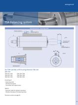
Vibration trabsducer Cable, standard length 3 m 97 Transmitter with speed sensor Cable, standard length 3 m Balancing motor
Open the catalog to page 25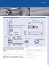
AC power input Vibration sensor Grinding wheel Speed sensor View A Balancing weigth Graduated collar Bracket
Open the catalog to page 27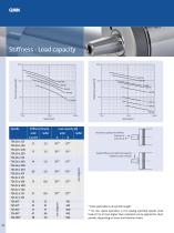
Radial load capacity [N] Axial load capacity [N] Axial load capacity and stiffness Direction A Direction B Radial stiffness and radial load capacity related to center of taper
Open the catalog to page 28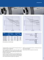
Radial load capacity [N] Axial load capacity [N] Axial load capacity and stiffness Direction A Direction B Radial stiffness and radial load capacity related to spindle nose
Open the catalog to page 29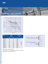
Radial load capacity [N] TSAV 200 TSAV 160 TSAV 140 TSAV 120 Load capacity Axial load capacity and stiffness in direction A and B is equal Radial stiffness and radial load capacity related to center of taper
Open the catalog to page 30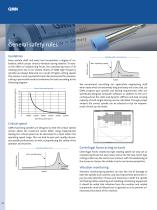
Vibration level Spindle with oversized tool Max. operating speed Permissible residual unbalance [gmm] Vibration level Spindle without tool Max. spindle speed 1. Critical speed Speed
Open the catalog to page 32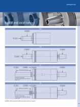
Distance of measuring: Five times taper dia. (k1) max. 100 mm (3.937 inch) Distance of measuring: Five times taper dia. (d) max. 100 mm (3.937 inch)
Open the catalog to page 33All GMN USA catalogs and technical brochures
 Oil/Air Lubricator PRELUB GP
2 Pages
 OIL-AIR LUBRICATOR PRELUB
2 Pages
 GMN USA BROCHURE
12 Pages


- Electromotor
- Electrical cable
- Synchronous motor
- Alternating current motor
- Chiller
- Power cable
- Liquid recirculation chiller
- Compact electromotor
- Water recirculation chiller
- Industrial cooling system
- Custom motor
- High-speed motor
- Precision motor
- Temperature monitoring module
- Connection electrical cable
- Motor driver
- Wireless monitoring module
- Milling spindle
- Robust electromotor
- Benchtop monitoring system