
Catalog excerpts

www.gminternational.com Intrinsically Safe Isolators > Analog Output D5020 I.S. SIL2 HART® Isolating Driver The Isolating Driver D5020 module is a high integrity analog output interface suitable for applications requiring SIL 2 level in safety related systems for high risk industries. It isolates and transfers a 420 mA signal from a controller located in Safe Area to a load in Hazardous Area. It has a high output capacity combined with a low drop across its input terminals. The circuit allows bi-directional communication signals, for HART® smart positioners. Line and load open/short circuit detection is provided: the fault in the field is directly mirrored to the PLC AO and it is also reported by opening the fault output. FEATURES SIL 2 / SC 3 Output to Zone 0/Div. 1 Installation in Zone 2/Div. 2 2 fully independent channels 4-20 mA Input, Output Signal HART® compatible Line & Load short/open circuit detection Field fault mirroring to the PLC AO In-field programmability by DIP Switch High Accuracy Three port isolation, Input/Output/Supply High Density, two channels per unit ORDERING INFORMATION Ordering codes D5020S: 1 channel D5020D: 2 channels Accessories Bus Connector JDFT049, Bus Mounting Kit OPT5096. OVERALL DIMENSIONS TECHNICAL DATA Supply 24 Vdc nom (18 to 30 Vdc), reverse polarity protected. Current consumption: 70 mA (D5020D), 35 mA (D5020S), @ 24 Vdc with 20 mA output on 500 Ω load, typical. Power dissipation: 1.3 W (D5020D), 0.65 W (D5020S), @ 24 Vdc with 20 mA output on 500 Ω load, typical. Input 4 to 20 mA with ≤ 2.5 V voltage drop, reverse polarity protected in normal operation, ≥ 5 kΩ impedance (≈ 2 mA sinking from 10 to 30 Vdc) when fault condition detected. Output 4 to 20 mA, on max. 700 Ω load. Response time: 25 ms (0 to 100 % step change). Fault Field device and wiring open circuit or short circuit detection; short circuit detection can be disabled via dip-switch. Short output: load resistance < 50 Ω or < 100 Ω dip-switch selectable (≈ 2 mA forcing to detect fault). Open output: load resistance > (21 V / Loop current) -300 Ω (for example, if Loop current = 20 mA: load resistance > (21 V / 20 mA) -300 Ω = 750 Ω). Fault signaling: voltage free NE SPST optocoupled open-collector transistor (output de-energized in fault condition). Open-collector/drain rating: 100 mA @ 35 Vdc (≤ 1.5 V voltage drop). Leakage current: ≤ 50 µA @ 35 Vdc. Response time: ≤ 30 ms. Performance Ref. Conditions: 24 V supply, 250 Ω load, 23 ± 1 °C ambient temperature. Calibration accuracy: ≤ ± 0.1 % FSR. Linearity accuracy: ≤ ± 0.1 % FSR. Temp. influence: ≤ ± 0.01 % FSR on zero/span for a 1 °C change. Isolation I.S. Out/In 2.5 kV; I.S. Out/Supply 2.5 kV; I.S. Out/Fault 2.5 kV; I.S. Out/I.S. Out 500 V; In/Supply 500 V; In/In 500 V; Fault/In 500 V; Fault/Supply 500 V; Fault/Fault 500 V. Environmental conditions Operating temperature: temperature limits –40 to +70 °C. Storage temperature: temperature limits –45 to +80 °C. Safety description Associated apparatus and non-sparking electrical equipment. Uo = 25.9 V, Io = 93 mA, Po = 595 mW at terminals 7-8, 9-10. Um = 250 Vrms or Vdc, -40 °C ≤ Ta ≤ 70 °C. Mounting DIN-Rail 35 mm, with or without Power Bus or on custom Term. Board. Weight: about 145 g (D5020D), 130 g (D5020S). Connection: by polarized plug-in disconnect screw terminal blocks to accommodate terminations up to 2.5 mm² (13 AWG). Dimensions: Width 12.5 mm, Depth 123 mm, Height 120 mm. Functional Safety Management Certification: GM International is certified to conform to IEC61508:2010 part 1 clauses 5-6 for safety related systems up to and included SIL3. In addition, GM International products have been granted I.S. certificates from the most credited Notified Bodies in the world. Data specified in this document are merely descriptive of the products and should be integrated with relevant technical specifications. Our products are in constant development and the information presented herein refers to the time of document issue. No statements concerning a certain condition or suitability for a certain application can be derived from our information. The information given does not release the user from the obligation of own judgment and verification. Terms & Conditions can be found at our website. For more information refer to istruction manual
Open the catalog to page 1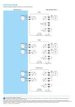
FUNCTION DIAGRAM Additional installation diagrams may be found in Instruction Manual. Hazardous Area Functional Safety Management Certification: GM International is certified to conform to IEC61508:2010 part 1 clauses 5-6 for safety related systems up to and included SIL3. In addition, GM International products have been granted I.S. certificates from the most credited Notified Bodies in the world. Data specified in this document are merely descriptive of the products and should be integrated with relevant technical specifications. Our products are in constant development and the...
Open the catalog to page 2All GM International srl catalogs and technical brochures
-
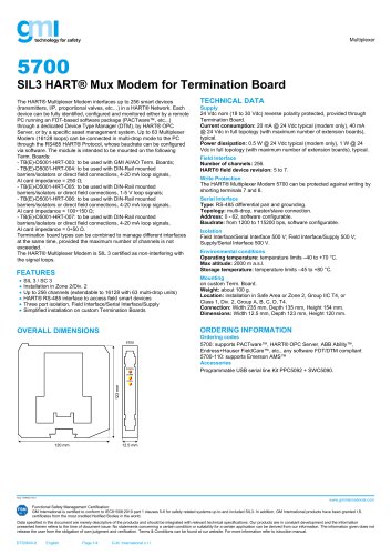 5700
57004 Pages
-
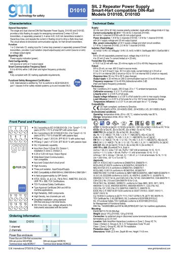 D1010
D10104 Pages
-
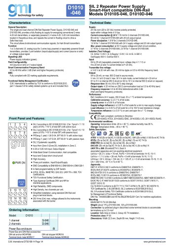 D1010 -046
4 Pages
-
 D1012
D10122 Pages
-
 D1022
D10222 Pages
-
 D1052
D10524 Pages
-
 D1061 -077
2 Pages
-
 D1072
D10726 Pages
-
 D1020
D10202 Pages
-
 D5030
D50302 Pages
Archived catalogs
-
 Models D5030S, D5030D
4 Pages
-
 Company Profile English
20 Pages
-
 Product overview
56 Pages