 Website:
GM International srl
Catalog excerpts
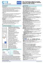
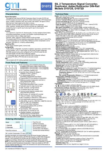
Technical Data: General Description: The single and dual channel DIN Rail Temperature Signal Converter D1072S and D1072D accepts a low level dc signal from millivolt, thermocouple or RTD temperature sensor, located in Hazardous Area, and converts, with isolation, the signal to drive a Safe Area load. Output signal can be direct or reverse. Duplicator function provides two independent outputs for the single input. Adder, subtractor, low/high selector functions provides two independent outputs representing input A, input B, input A plus input B, input A minus input B, low/high selector. Function: 1 or 2 channel I.S. input from mV, thermocouples, 3-4 wires resistance thermometers, transmitting potentiometers, provides 3 port isolation (input/output/supply) and current (source mode) or voltage output signal. Duplicator, adder, subtractor, low/high selector function provided. The programmable RTD line resistance compensation allows the use of 2 wires RTDs or error compensation for 3-4 wires RTDs. Reference junction compensation can be automatic, with option 91, or fixed by software setting. Signalling LEDs: Power supply indication (green), burnout (red). Configurability: Totally software configurable, no jumpers or switches, input sensor, connection mode, burnout operation, mA or V output signal, by GM Pocket Portable Configurator PPC1090, powered by the unit or configured by PC via RS-232 serial line with PPC1092 Adapter and SWC1090 Configurator software. A 16 characters tag can be inserted using SWC1090 Configurator software. To operate PPC1090 or PPC1092 refer to instruction manual. EMC: Fully compliant with CE marking applicable requirements. Front Panel and Features: SIL 2 according to IEC 61508:2010 (Route 2H) for analog current source output of each channel 1 2 3 4 5 D1072S:Tproof = 3/10 yrs (≤10% / >10 % of total SIF) D1072D:Tproof = 3/10 yrs (≤10% / >10 % of total SIF) SC2 : Systematic Capability SIL2. Input from Zone 0 (Zone 20), Division 1, installation in Zone 2, Division 2. mV, thermocouples, RTD or transmitting potentiometers Input Signal. Programmable RTD line resistance compensation. Reference Junction Compensation automatic or fixed (programmable value). 0/4-20 mA, 0/1-5 V, 0/2-10 V Output Signal temperature linear or reverse. Duplicated output for single channel input. Adder, Subtractor, low/high Selector. 16 characters tag for each channel. Common burnout detection available when using Power Bus enclosure. High Accuracy, µP controlled A/D converter. Three port isolation, Input/Output/Supply. EMC Compatibility to EN61000-6-2, EN61000-6-4. Fully programmable operating parameters. ATEX, IECEx, UL & C-UL, FM & FM-C, INMETRO, EAC-EX, UKR TR n. 898, TÜV Certifications. TÜV Functional Safety Certification. Type Approval Certificate DNV and KR for maritime applications. High Reliability, SMD components. High Density, two channels per unit. Simplified installation using standard DIN Rail and plug-in terminal blocks. 250 Vrms (Um) max. voltage allowed to the instruments associated with the barrier. Ordering Information: Model: 1 channel 2 channels Power Bus enclosure SIL 2 Temperature Signal Converter, Duplicator, Adder/Subtractor DIN-Rail Models D1072S, D1072D Power Bus and DIN-Rail accessories: DIN rail anchor MCHP065 DIN rail stopper MOR016 Terminal block male MOR017 Terminal block female MOR022 Ref. Junction Compensator (TC input) OPT1091 Operating parameters are programmable by the GM Pocket Portable Configurator PPC1090 or via RS-232 serial line with PPC1092 Adapter and SWC1090 Configurator software. If the parameters are provided with the purchasing order the unit will be configured accordingly, otherwise the unit will be supplied with default parameters. NOTE: for thermocouple sensor input, the Reference Junction Compensator is required for automatic ambient temperature compensation. It has to be ordered as OPT1091, it will be supplied separately and it has to be connected to the input terminal blocks as indicated in the function diagram. G.M. International DTS0025-27 Page 1/6 Supply: 12-24 Vdc nom (10 to 30 Vdc) reverse polarity protected, ripple within voltage limits ≤ 5 Vpp. Current consumption @ 24 V: 70 mA for 2 channels D1072D, 45 mA for 1 channel D1072S with 20 mA output typical. Current consumption @ 12 V: 140 mA for 2 channels D1072D, 80 mA for 1 channel D1072S with 20 mA output typical. Power dissipation: 1.5 W for 2 channels D1072D, 1.0 W for 1 channel D1072S with 24 V supply voltage and 20 mA output typical. Max. power consumption: at 30 V supply voltage, overload condition and PPC1090 connected, 2.1 W for 2 channels D1072D, 1.4 W for 1 channel D1072S. Isolation (Test Voltage): I.S. In/Out 1.5 KV; I.S. In/Supply 1.5 KV; I.S. In/I.S. In 500 V; Out/Supply 500 V; Out/Out 500 V. Input: millivolt or thermocouple type A1, A2, A3, B, E, J, K, L, Lr, N, R, S, S1, T, U or 3-4 wires RTD Pt100, Pt200, Pt300 to DIN43760, Pt100 (0.3916), Ni100, Ni120 or Pt500, Pt100, Pt50, Cu100, Cu53, Cu50, Cu46 (russian standard) or 3 wires transmitting potentiometer (50 Ω to 20 KΩ). Integration time: 500 ms. Resolution: 5 µV on mV or thermocouple, 1 µV thermocouple type B, R, S, S1, 2 µV thermocouple A1, A2, A3, 20 mΩ on RTD, 0.05 % on transmitting potentiometer. Visualization: 0.1 °C on temperature, 10 µV on mV, 0.1 % on potentiometer. Input range: within rated limits of sensor (-10 to + 80 mV). Measuring RTD current: ≤ 0.5 mA. RTD line resistance compensation: ≤ 10 Ω. RTD line resistance error compensation: - 5 to + 20 Ω, programmable. Thermocouple Reference Junction Compensation: automatic, by external sensor OPT1091 separately ordered, or fixed programmable from - 60 to + 100 °C. Thermocouple burnout current: ≤ 30 nA. Burnout: enabled or disabled. Analog output can be programmed to detect burnout condition with downscale or highscale forcing. Burnout condition signalled by red front panel LED. Output: 0/4 to 20 mA, on max. 600 Ω load source mode, current limited at 22 mA or 0/1 to 5 V or 0/2 to 10 V signal, limited at 11 V. Resolution: 2 µA current output or 1 mV voltage output. Transfer characteristic: linear or reverse on mV or transmitting potentiometer, temperature linear or reverse on temperature sensors. Response time: ≤ 50 ms (10 to 90 % step change). Output ripple: ≤ 20 mVrms on 250 Ω load. Performance: Ref. Conditions 24 V supply, 250 Ω load, 23 ± 1 °C ambient temperature. Input: Calibration and linearity accuracy: ≤ ± 40 µV on mV or thermocouple, 200 mΩ on RTD, 0.2 % on potentiometer or ± 0.05 % of input value. Temperature influence: ≤ ± 2 µV, 20 mΩ, 0.02 % or ± 0.01 % of input value for a 1 °C change. Ref. Junction Compensation influence: ≤ ± 1 °C (thermocouple sensor). Analog Output: Calibration accuracy: ≤ ± 0.1 % of full scale. Linearity error: ≤ ± 0.05 % of full scale. Supply voltage influence: ≤ ± 0.05 % of full scale for a min to max supply change. Load influence: ≤ ± 0.05 % of full scale for a 0 to 100 % load resistance change. Temperature influence: ≤ ± 0.01 % on zero and span for a 1 °C change. Compatibility: CE mark compliant, conforms to Directive: 2014/34/EU ATEX, 2014/30/EU EMC, 2014/35/EU LVD, 2011/65/EU RoHS. Environmental conditions: Operating: temperature limits -20 to + 60 °C, relative humidity max 90 % non condensing, up to 35 °C. Storage: temperature limits – 45 to + 80 °C. Safety Description: ATEX: II (1)G [Ex ia Ga] IIC, II (1)D [Ex ia Da] IIIC, I (M1) [Ex ia Ma] I, II 3G Ex ec IIC T4 Gc IECEx: [Ex ia Ga] IIC, [Ex ia Da] IIIC, [Ex ia Ma] I, Ex ec IIC T4 Gc INMETRO: [Ex ia Ga] IIC, [Ex ia Da] IIIC, [Ex ia Ma] I Uo/Voc = 10.8 V, Io/Isc = 9 mA, Po/Po = 24 mW at terminals 13-14-15-16, 9-10-11-12. Ui/Vmax = 18 V, Ci = 6 nF, Li = 0 nH at terminals 13-14-15-16, 9-10-11-12. Um = 250 Vrms, -20 °C ≤ Ta ≤ 60°C. Approvals: DMT 01 ATEX E 042 X conforms to EN60079-0, EN60079-11. IECEx BVS 07.0027X conforms to IEC60079-0, IEC60079-11. IMQ 09 ATEX 013 X conforms to EN60079-0, EN60079-7. IECEx IMQ 13.0011X conforms to IEC60079-0, IEC60079-7. INMETRO DNV 13.0108 X conforms to ABNT NBR IEC60079-0, ABNT NBR IEC60079-11. UL & C-UL E222308 conforms to UL913, UL 60079-0, UL60079-11, UL60079-15, ANSI/ISA 12.12.01 for UL and CSA-C22.2 No.157-92, CSA-E60079-0, CSA-E60079-11, CSA-C22.2 No. 213 and CSA-E60079-15 for C-UL. FM & FM-C No. 3024643, 3029921C, conforms to Class 3600, 3610, 3611, 3810, ANSI/ISA 12.12.02, ANSI/ISA 60079-0, ANSI/ISA 60079-11, C22.2 No.142, C22.2 No.157, C22.2 No.213, E60079-0, E60079-11, E60079-15. ЕАЭС RU С-IT.HA67.B.00113/20 conforms to GOST 31610.0, GOST 31610.11, GOST 31610.15. CЦ 16.0034 X conforms to ДСТУ 7113, ГОСТ 22782.5-78, ДСТУ IЕС 60079-15. TÜV Declaration of Compliance No. C-IS-722238330, SIL 2 according to IEC 61508:2010 Ed.2. SIL 3 Functional Safety TÜV Certificate conforms to IEC61508:2010 Ed.2, for Management of Functional Safety. DNV No. TAA00002BM and KR No.MIL20769-EL001 Cert. for maritime applications. Mounting: EN/IEC60715 TH 35 DIN-Rail. Weight: about 170 g D1072D, 140 g D1072S. Connection: by polarized plug-in disconnect screw terminal blocks to accomodate terminations up to 2.5 mm2. Location: Safe Area/Non Hazardous Locations or Zone 2, Group IIC T4, Class I, Division 2, Grou
Open the catalog to page 1All GM International srl catalogs and technical brochures
-
5700
4 Pages
-
D1010
4 Pages
-
D1010 -046
4 Pages
-
D1012
2 Pages
-
D1022
2 Pages
-
D1052
4 Pages
-
D1061 -077
2 Pages
-
D5020
2 Pages
-
D1020
2 Pages
-
D5030
2 Pages
Archived catalogs
-
Models D5030S, D5030D
4 Pages
-
Company Profile English
20 Pages
-
Product overview
56 Pages

