
- Catalogs
- GM International S.p.A.
- SIL Poster


- Company
- Products
- Catalogs
- News & Trends
- Exhibitions
SIL Poster
SIL Poster
Catalog excerpts
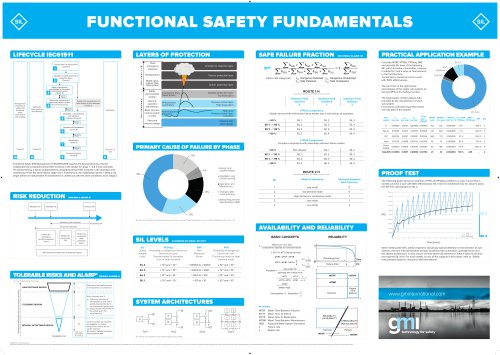
FUNCTIONAL SAFETY FUNDAMENTALS Hazard and risk assessment Clause 8 Allocation of safety functions to protection layers Clause 9 Emergency response layer Passive protection layer Relief valve, rupture disk, F&G system Active protection layer Failure rate categories: ADD: Dangerous Detected; ADU: Dangerous Undetected; Asd: Safe Detected; ASU: Safe Undetected. Safety requirements specification for the safety instrumented system Clause 10 Management of functional safety and functional safety assessment and auditing Design and engineering of safety instrumented system Clauses 11, 12 and 13 Safety lifecycle structure and planning Design and development of other means of risk reduction Clause 9 Installation, commissioning and validation Clauses 14 and 15 Operation and maintenance Clause 16 Alarm & operator intervention Basic process control system or DCS Plant and process design (for further information see 61508-2 Clause 74.4.2) Hardware Fault Tolerance 0 Hardware Fault Tolerance 1 Hardware Fault Tolerance 2 Simple devices with well-known failure modes and a solid history of operation Calculate MTBF, MTBFs, PFDavg, RRF, and possible SIL level of the following SIF, which includes a transmitter, a barrier, a safety PLC, and a valve as final element, in 1oo1 architecture. T-proof test is carried out once a year with 100% effectiveness. The pie chart on the right shows percentages of the single sub-systems on the total PFD of the Safety Function. The table below contains failure data provided by the manufacturer of each sub-system. Formulae to calculate requested values are indicated in the header. Inherent safe plant design PRIMARY CAUSE OF FAILURE BY PHASE Complex components with potentially unknown failure modes system per year per year per year MTBF MTBFs= PFDavg % of Total RRF= Functional Safety (FS) Management in IEC61511:2016 requires FS Assessments by a Senior independent & competent person NOT involved in the design for stage 1 - 2 & 3 and a periodic FS assessment by a Senior independent & competent person NOT involved in the operation and maintenance from the same SIS for stage 4 & 5. Furthermore, the modification phase 7 SHALL not begin before an independent FS assessment is carried out with the same conditions as for stage 5. Changes after commissioning Safety Requirement Specifications (SRS) Ref.: Out of control: Why control systems go wrong and how to prevent failure? (2nd edition, source: © Health & Safety Executive HSE - UK) (for further information see 61508-2 Clause 74.4.3) Minimum Hardware Fault Tolerance high demand or continuous mode PROOF TEST The following graph shows an example of PFD and PFDavg variations in case T-proof test is carried out once a year with 80% effectiveness: SIL 3 level is maintained only for about 5 years; the SIF then downgrades to SIL 2. Risk reduction achieved by all protection layers Safety Probability of dangerous Failure on Demand per year. Demand mode of operation (Low or High demand) Probability of dangerous Failure per hour. Continuous mode or High demand mode BASIC CONCEPTS Failures per unit time Components exposed to functional failure 1 FIT _ 1x 10⁻⁹ Failures per hour MTBF = MTTF + MTTR MTTF _ MTBF -MTTR _ When dealing with SIFs, safety engineers should pay special attention to the selection of subsystems, the time interval between periodic proof test with achievable coverage factor and the system architecture. A wise choice of these three key elements is what it takes to achieve the required SIL level. For more details on any of the subjects in this poster, refer to “Safety Instrumented Systems” manual by GM International. Operating Time TOLERABLE RISKS AND ALARP* (IEC61511-3 ANNEX K) Operating Time+ Repair Time MTTF MTTF p UNACCEPTABLE REGION Risk cannot be justified except in extraordinary circumstances MTTF + MTTR MTBF p + A MTBM TOLERABLE REGION Negligible risk Risk Class (see Tables K.1 and K.2) Risk is tolerable only if: a) further risk reduction is impracticable or if its cost is grossly disproportionate to the improvement gained and b) society desires the benefit of the activity given the associated risk Level of residual risk regarded as negligible and further measures to reduce risk not usually required. No need for detailed working to demonstrate ALARP SYSTEM ARCHITECTURES MTBF Mean Ti meBetween Failures MTTF M eanTimeToFailure MTTR Mean Time ToRestoration MTB M Mea n Time Between Maintenance MSD Expected Mean System Downtime A Failure rate All contacts are considered in open (De-energize to trip) condition. Information presented in this poster is for the general education of the reader. GM International does not have control over the use of the information by the readers therefore GM International disclaims any and all liability of any kind arising out of such use. Examples are provided as simple illustrations of the topics and, as such, are not intended as a guide to manage plant safety. The readers should use and apply only the guidance provided in the standards pertaining to their applications. The reproduction by any means, partial or total, of the poster and its content is prohibited without making a clear reference to the original source.
Open the catalog to page 1
Functional Safety Fundamentals MSD0017-01 © G.M. International s.r.l. Information presented in this poster is for the general education of the reader. GM International does not have control over the use of the information by the readers therefore GM International disclaims any and all liability of any kind arising out of such use. Examples are provided as simple illustrations of the topics and, as such, are not intended as a guide to manage plant safety. The readers should use and apply only the guidance provided in the standards pertaining to their applications. The reproduction by any means,...
Open the catalog to page 2All GM International S.p.A. catalogs and technical brochures
 Product Overview
58 Pages
 X1 SERIES
4 Pages
 GMI D5000-D5200 Datasheets
154 Pages
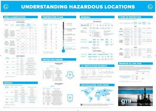 EX Poster
2 Pages
- Connector
- GM International power supply
- GM International DC power supply
- Data connector
- AC/DC power supply
- Surge protector
- GM International digital I/O
- GM International terminal block
- Socket electrical connector
- Single-output power supply
- DIN rail lightning arrester
- Male connector
- Switched-mode power supply
- Compact power supply
- Signal amplifying integrated circuit
- Tabletop power supply
- DIN rail power supply
- DIN connector
- Variable-output power supply
- Power supply with overload protection