
- Catalogs
- GLOBE Airmotors, Test Equipment & Motion Control
- Rod Lock data sheet

- Company
- Products
- Catalogs
- News & Trends
- Exhibitions
Rod Lock data sheet

Rod Lock data sheet
- Dynamic Stopping Distance: 0.040 meters
- E-stop travel distance must be less than 100 mm
- Rod locks should be used sparingly to prevent wear and performance reduction.
Catalog excerpts

Certified Safety Products LINEAR MOTION CONTROL Technical Data Sheet NexSafe™ Safety Rated Rod Lock: Spring Engaged, Air Released • SAFE-RLSSB-S: Stand Alone Version • SAFE-RLSSB-C: Cylinder Mount Version Options: Manual Release & Sensors Available
Open the catalog to page 1
A New Standard In Performance Nexen’s new generation of linear holding/locking devices take rod locking technology to the next level. With superior performance, these spring-engaged, air-released units supplement air cylinders and guide rods for holding in power-off/e-stop situations. High clamping forces ensure positive holding with minimal air required for release. Choose from our standard products, or we will work with you to meet your unique application specifications. Certified Safety Products Nexen’s Spring Engaged, Air Released Rod Locks are safety rated to comply with international safety...
Open the catalog to page 2
Nexen’s Static Rod Locks deliver precision holding with virtually no backlash, providing high accuracy in demanding applications. These spring-engaged, air-released units come in both ISO and NFPA sizes and will accept standard accessories. The Rod Lock’s large clamping surface ensures high clamping/holding force and Nexen offers models for use on a pneumatic cylinder or as a stand-alone unit on a guide rod. Customers can further increase holding forces by stacking multiple Rod Locks together. The patented design is sealed and features a natural brushed aluminum finish or a corrosion-resistant,...
Open the catalog to page 3
Stand-Alone Rod Locks for Guide Rod Applications Round Guide Rod Application Stand-Alone Rod Lock Specifications Inch Rod Locks Rod Diameter Holding Force Anodized P/N Natural Finish P/N *Currently not safety rated, contact Nexen for safety version. Metric Rod Locks Rod Diameter Holding Force Anodized P/N Natural Finish P/N Locking Mode Sensors Sinking (NPN) Normally Open Sourcing (PNP) Normally Open Contact Nexen if two sensor slots are required for your application. 4
Open the catalog to page 4
Cylinder Mounted Rod Locks Nexen’s cylinder mounted RLSS Rod Locks match the cylinder profiles for easy, compact integration. Cylinder Requirements • Longer cylinder rod Extra length = rod lock length (F) – cylinder pilot length (for dimensions, see pages 9 & 11) • Hardened rod (preferred) or hard chrome plating: See Requirements for Optimal Performance for specifications. • Longer tie rods on NFPA cylinders • Mounting bolts included with ISO cylinders Cylinder Mounted Rod Lock Specifications NFPA Rod Locks, ‘FM’ Mounts Rod Diameter Bore Size Holding Force *Currently not safety rated, contact...
Open the catalog to page 5
Rod Lock Operation Specifications All of Nexen’s Rod Locks will operate in both directions, engaging with the same holding force. Rod Locks can be mounted in any position. Rod rotation is not allowed when a Rod Lock is engaged (not intended for torsional braking). Nexen’s Rod Lock complies with ISO 15552 standards. Release pressures can range from 4–8 bar [60–120 psi]. The Buna-N seals used are rated to 100°C [212°F]. Allowable operating temperatures range from 4.5°C–65.5°C [40°F–150°F]. Units are capable of intermittent use at temperatures up to 100°C [212°F]. Nexen’s Rod Lock cycle life B10...
Open the catalog to page 6
Air Controls and Programming Note: neumatic components are in accordance with ISO 4414 P Minimum release pressure = 4 bar [60 psi] Maximum pressure = 8 bar [120 psi] Optional Solenoid Valves Specifications Description Voltage Port Size 3-way Solenoid Valve, NC 24 VDC .125-27 NPT 3-way Solenoid Valve, NC 24 VDC .125-28 BSPP 3-way Solenoid Valve, NC 115 V .125-27 NPT CYLINDER MOUNTING NOTE: Avoid repeated overlapping conditions when programming the Rod Lock into your system. (i.e.: forced motion during engagement or disengagement of the Rod Lock.) Shaft and/or collar wear will result. Design the...
Open the catalog to page 7
Stand-Alone Rod Locks for Inch Guide Rods, Approximate Dimensions Dimensions shown in inches. Vent/Breather J NPTF Air Inlet * "T-Slot" for Inductive Sensor Contact Nexen if one or more of these dimensions must be modified for your application. A Allowable Shaft Diameter Seals and Bearings Both Ends * Available with up to two sensor slots. RLSSB Model Contact Nexen if two sensor slots are required for your application. +.000 Product B Number øA -.002 (to slot) øBC Stand-alone Rod Locks for Metric Guide Rods, Approximate Dimensions J Dimensions shown in millimeters. Contact Nexen if one or more...
Open the catalog to page 8
Rod Locks for NFPA Cylinders, Approximate Dimensions Vent/Breather Dimensions shown in inches. * "T-Slot" for Inductive Sensor H * Available with up to two sensor slots. +.000 Product B Number øA -.002 (to slot) øBC Contact Nexen if two sensor slots are required for your application. A Allowable Shaft Diameter Seal and Bearing Single End RLSSB Model Contact Nexen if one or more of these dimensions must be modified for your application. Rod Locks for ISO Cylinders, Approximate Dimensions Dimensions shown in millimeters. Vent/Breather J BSPP(G) Air Inlet Contact Nexen if one or more of these dimensions...
Open the catalog to page 9
Rod Locks with Manual Release For NFPA and ISO Cylinders Manual Release Specifications • Cam operated, default to the lock function • No special tools needed for manual disengagement, uses standard size hex head • Stainless steel disengagement screw • Locking mode feedback sensor (optional) • Tested and rated to 5,000 cycles Manual Release NFPA Cylinder Operating Mode Sensor Approximate Engagement Time (te) (seconds) Rated Holding Force (F) (lbs) Minimum Torque to Override (ft-lbs) Anodized Product Number Natural Product Number * RLSS 800-250-C-MR 8.00 17.53 0.210 * These products do not have...
Open the catalog to page 10
Rod Locks w/ Manual Release for NFPA and ISO Cylinders, Approximate Dimensions Vent/Breather Product numbers on previous page. Contact Nexen if one or more of these dimensions must be modified for your application. "T-Slot" For Inductive Sensor Contact Nexen if two sensor slots are required for your application. Seal and Bearing Single End A Allowable Shaft Diameter * Available with up to two sensor slots. NFPA (Dimensions shown in inches) Description * These products do not have operating mode T slot provisions. ISO (Dimensions shown in millimeters) Description
Open the catalog to page 11All GLOBE Airmotors, Test Equipment & Motion Control catalogs and technical brochures
 Gear air motor CVM10 series
15 Pages
 Vane air motor V12 series
24 Pages
 Vane air motor V10 series
28 Pages
 Vane air motor V8 series
28 Pages
 Vane air motor V6 series
28 Pages
 Vane air motor V4 series
28 Pages
 Vane air motor V2 series
28 Pages
 Vane air motor V1 series
24 Pages
 GLOBE RM024 Specifications
4 Pages
 GLOBE RM012 Specifications
5 Pages
 GLOBE RM006 Specifications
4 Pages
 GLOBE RM004 Specifications
4 Pages
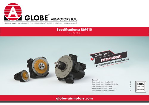
 GLOBE Specifications RM410
7 Pages
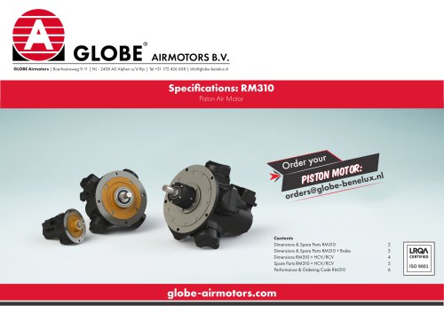
 GLOBE Specifications RM310
7 Pages
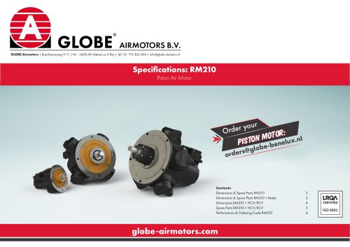
 GLOBE Specifications RM210
7 Pages
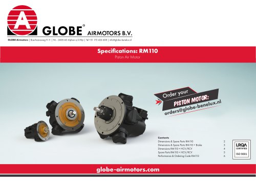
 GLOBE Specifications RM110
7 Pages
 GLOBE Compact Vane Air Motor
8 Pages
 APU Unicub Systems
5 Pages
 GLOBE FRL units
5 Pages
 GLOBE High Flow Silencers
2 Pages
 GLOBE BN brakes
4 Pages
 GLOBE geared vane air motors
21 Pages
 Compact piston air motors
28 Pages
 GLOBE Piston Air Motors
64 Pages


Archived catalogs
 Air Motor unit for Winches
9 Pages
 GLOBE APU MK-7 Systems
5 Pages
 Zero backlash gearing catalog
30 Pages
 Shaft brake datasheet
9 Pages
 GLOBE Vane Air Motors
48 Pages
 Servomotor brake data sheet
23 Pages
 Ring Drive systems catalog
32 Pages
 Roller Pinion System Catalog
56 Pages
 Guide rail brake catalog
13 Pages
 Ball screw brake data sheet
4 Pages
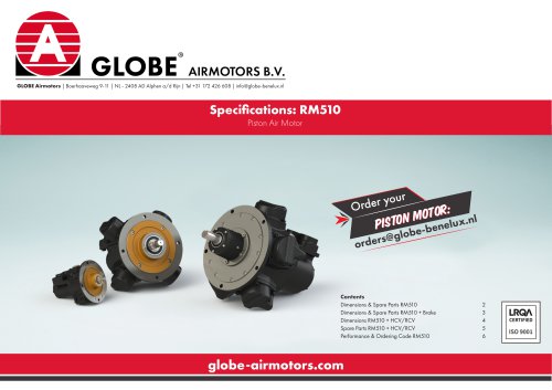
 GLOBE Specifications RM510
7 Pages
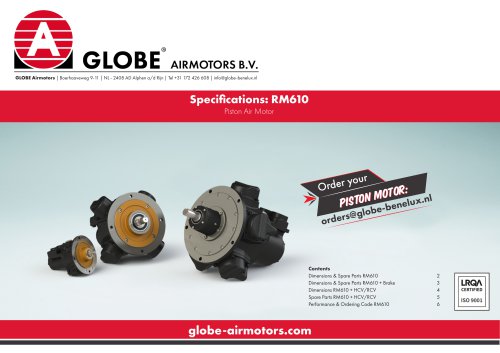
 GLOBE Specifications RM610
7 Pages
 GLOBE Airmotors
103 Pages
 ZERO BACKLASH GEARING
30 Pages
 LINEAR MOTION CONTROL
4 Pages
 Stepper Motor
2 Pages
 Air motors for power packs
5 Pages
 PFG-series
26 Pages
 Pneumaticstepping motors
2 Pages
 Special silencers
1 Page
 Air operated gas boosters
20 Pages


