- Catalogs
- GLOBE Airmotors, Test Equipment & Motion Control
- Ring Drive systems catalog
- Company
- Products
- Catalogs
- News & Trends
- Exhibitions
Ring Drive systems catalog
1 /32Pages

Ring Drive systems catalog
1 /32Pages
Catalog excerpts
Features & Benefits Application & Selection Guide 2 Selection Process (CRD) Compact Precision Ring Drive Based on Nexen’s innovative Roller Pinion technology, Nexen Ring Drive Systems come complete with a precision grade, high capacity bearing and drive mechanism in a rigid housing. With options for high speed, high torque and zero backlash, Nexen Ring Drives can be optimized for every application. With accelerations up to twice as high as other indexing technologies, Nexen Ring Drive systems provide more productivity while boasting low maintenance, high efficiency and long life. PRECISION RING DRIVE TECHNOLOGY PRECISION RING DRIVE SYSTEMS (PRD) Precision Ring Drive The most advanced technology in rotary motion control. PATENTED
Open the catalog to page 1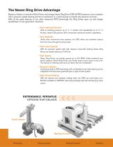
The Nexen Ring Drive Advantage Based on Nexen’s innovative Roller Pinion technology, Nexen Ring Drive (CRD & PRD) systems come complete with a precision grade bearing and drive mechanism in a rigid housing to simplify the selection process. With all the great features of our other advanced RPS technology, the Ring Drives open up new design possibilities to next generation machines. • High Indexing Precision With an indexing precision up to ± 11 ArcSec and repeatability up to ± 1.2 ArcSec, Nexen’s Ring Drives offer unmatched mechanical system capabilities. • Zero Backlash Unlike other mechanical...
Open the catalog to page 2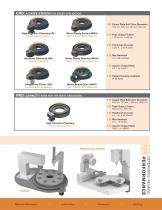
CRD: A DRIVE STATION FOR EVERY APPLICATION acklash low b backlash zero Output Plate Bolt Circle Diameters 150 mm, 250 mm, 350 mm, 550 mm High Precision Planetary (PL) Flexible Gearhead Ratio zero Motor Ready Sealed (MRS) Ready to Accept Motor/Gearhead Peak Output Torque 119 Nm to 1148 Nm Positional Accuracy ± 20 to ± 59 ArcSec Max Backlash Harmonic Gearhead (HG) High Ratio Gearhead zero Motor Ready Guarded (MRG) Ready to Accept Motor/Gearhead Input to Output Ratio Sealed Housing Available IP 65 Rated Direct Drive Pinion (DD) Integrated Motor, No Gearhead Motor Ready Open (MRO) Ready to Accept...
Open the catalog to page 3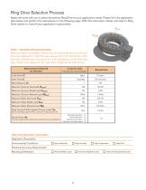
Ring Drive Selection Process Nexen will work with you to select the perfect Ring Drive for your application needs. Please fill in the application data below and perform the calculations on the following page. With this information, Nexen will select a Ring Drive system to meet all your application requirements. Faxial Fradial TM STEP 1: GATHER APPLICATION DATA Before you begin calculations, there are key measurements that you will need from your application. Collect the data and record it in the chart below. With this data available you can proceed on to the calculations on the following page....
Open the catalog to page 4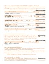
STEP 2: CALCULATING RING DRIVE REQUIREMENTS FOR SIMPLE INDEXING APPLICATIONS Ring Drive selection is based on the torque requirements of your application. Using the information gathered on the preceding page, perform the following calculations. If your application movement is more complex than basic indexing, evaluate each stage of movement independently and perform separate calculations for each stage. Acceleration Time Sample: tA = 0.9 seconds ÷ 2 = 0.45 seconds Max Angular Speed Max Angular Speed: w = (q ÷ tI) • (� ÷ 90) Sample: Angular Acceleration Angular Acceleration: Sample: 1.75 rad/sec...
Open the catalog to page 5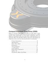
Compact Precision Ring Drive (CRD) Based on innovative Roller Pinion technology, the CRD system comes complete with a precision grade bearing and drive mechanism in a sealed housing. Freely programmable, the drive design configurations allow the CRD to be optimized for high speed, high torque or both depending on the application. With a 150, 250, 350 or 550 mm output bolt circle diameter and a large open center, users can optimize performance in a small space.
Open the catalog to page 7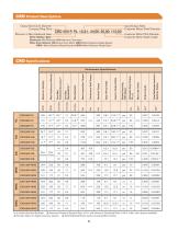
CRD Product Descriptions Output Bolt Circle Diameter Compact Ring Drive Premium or Non-Hardened Gear Drive Station Type: Gearboxes: PL=Planetary, HG=Harmonic Gearhead Other Drive Stations: DD=Direct Drive Motor, MRS=Motor/Gearbox Ready-Sealed, MRG= Motor/Gearbox Ready-Guarded, MRO=Motor/Gearbox Ready-Open Input/Output Ratio Customer Motor Shaft Diameter Customer Motor Pilot Diameter Customer Motor Shaft Length Total Reflected Inertia to Gearbox Output Input to Output Ratio Gear/Pinion Ratio Nominal Torque Unloaded Drag Torque (ULdrag) Continuous Stall Torque Sealed Housing, IP65 Rated One-Way...
Open the catalog to page 8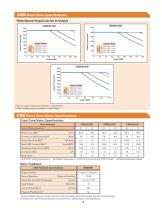
CRD Direct Drive Specifications 600 Motor Winding Motor Winding Motor Winding Peak Speed Torque Curves at500 Output For non-cyclic continuous operation, contact Nexen. 0 Direct Drive 60 80 Specifications Motor 100 Other winding options available, contact Nexen. 120 140 160 0 20 40 Motor Winding Motor Winding Motor Winding CRD Direct Drive Motor Specifications Direct Drive Motor Specifications Specifications Motor Winding Selection Continuous Stall Current (lc) 700 Torque Sensitivity (Kt) 600 Resistance (Line Supply Voltage to Line) (Rm) 300 Motor Winding Motor Feedback (2) Winding temperature...
Open the catalog to page 9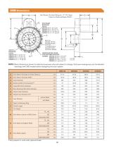
Not Shown: Air Inlet Fitting for .17" I.D. Hose. (Used on Optional Brake ONLY.) GREASE FITTING 2 AT 180° (1 ACCESS HOLE ON UNITS WITH OPTIONAL BRAKE) NOTE: Basic dimensions shown for selection purposes only and subject to change. Visit www.nexengroup.com for detailed drawings and CAD models before designing into your system. CRD150 Drive Station Envelope to Center Distance Drive Station Envelope Width Outer Diameter Stationary Bolt Circle Diameter Output Bolt Circle Diameter Base Mounting Hole Circle Diameter Output Outer Diameter Output Inner Diameter (H7) MOTOR FACE REQUIREMENTS I Inner Diameter...
Open the catalog to page 10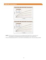
CRD150 Timing Diagrams CRD150P-MR (MRS, MRG, MRO) Timing Diagram CRD150-MR Timing Diagram CRD150-MR Timing Diagram CRD150N-MR Timing Diagram CRD150N-MR Timing Diagram NOTES: Curves assume no external forces such as additional table support friction, cutting forces, etc. Output Load Inertia 2.5 Timing diagrams are developed assuming minimum drag torque, use for reference only. 2.0 1 kg•m Output Load Inertia 5 kg•m Assumes Planetary Gearbox Ratio of 4:1 and Harmonic Gearhead Ratio of 50:1 (other ratio options available) 1 kg•m 10 kg•m 2.0 2 2 2 CRD250-MR T CRD250-MR T Output Load Inertia
Open the catalog to page 11All GLOBE Airmotors, Test Equipment & Motion Control catalogs and technical brochures
 GLOBE RM024 Specifications
4 Pages
 GLOBE RM012 Specifications
5 Pages
 GLOBE RM006 Specifications
4 Pages
 GLOBE RM004 Specifications
4 Pages
 GLOBE Specifications RM410
7 Pages
 GLOBE Specifications RM310
7 Pages
 GLOBE Specifications RM210
7 Pages
 GLOBE Specifications RM110
7 Pages
 GLOBE Compact Vane Air Motor
8 Pages
 APU Unicub Systems
5 Pages
 GLOBE FRL units
5 Pages
 GLOBE High Flow Silencers
2 Pages
 GLOBE BN brakes
4 Pages
 GLOBE geared vane air motors
21 Pages
 Compact piston air motors
28 Pages
 GLOBE Piston Air Motors
64 Pages


Archived catalogs
 Air Motor unit for Winches
9 Pages
 GLOBE APU MK-7 Systems
5 Pages
 Zero backlash gearing catalog
30 Pages
 Shaft brake datasheet
9 Pages
 Rod Lock data sheet
16 Pages
 GLOBE Vane Air Motors
48 Pages
 Servomotor brake data sheet
23 Pages
 Roller Pinion System Catalog
56 Pages
 Guide rail brake catalog
13 Pages
 Ball screw brake data sheet
4 Pages
 GLOBE Specifications RM510
7 Pages
 GLOBE Specifications RM610
7 Pages
 GLOBE Airmotors
103 Pages
 ZERO BACKLASH GEARING
30 Pages
 LINEAR MOTION CONTROL
4 Pages
 Stepper Motor
2 Pages
 Air motors for power packs
5 Pages
 PFG-series
26 Pages
 Pneumaticstepping motors
2 Pages
 Special silencers
1 Page
 Air operated gas boosters
20 Pages


- Liebherr pump
- Liebherr industrial pump
- Liebherr valve
- Liebherr electric pump
- Liebherr stationary pump
- Liebherr water pump
- Liebherr piping
- Liebherr centrifugal pump
- Liebherr self-priming pump
- Liebherr control valve
- Liebherr hydraulic fitting
- Liebherr screw-in fitting
- Liebherr stainless steel pump
- Lubricant pump
- Liebherr pneumatic valve
- Liebherr oil pump
- Liebherr threaded valve
- Liebherr regulating valve
- Liebherr shut-off valve