


- Company
- Products
- Catalogs
- News & Trends
- Exhibitions
ST02
ST02
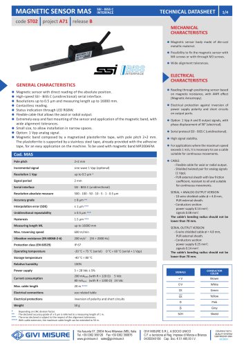
The magnetic sensor body is constructed from die-cast metallic material and can be mounted using M4 or M3 screws. It features wide alignment tolerances and utilizes a positioning sensor based on magneto resistance with AMR effect. The sensor includes electrical protection against power supply polarity inversion and short circuits.
The sensor provides direct reading of absolute position with a high-speed SSI - BiSS C serial interface. It offers resolutions up to 0.5 μm and a measuring length up to 16000 mm. The sensor is contactless and includes an RGBW LED for status indication. It supports flexible cable outputs and is designed for easy installation in narrow spaces.
The sensor uses a magnetized plastoferrite tape with a pole pitch of 2+2 mm, supported by a stainless steel tape for easy application. It is compatible with the magnetic band MP200AFM and offers a protection class of IP 67.
The SSI interface supports binary and Gray code with signal levels conforming to EIA RS 422. The BiSS C interface is unidirectional with a clock frequency up to 8 MHz. The maximum cable length is 20 m, extendable to 50 m with proper cable extension.
Graphs indicate the sensor's interpolation accuracy, position accuracy, and repeatability under controlled conditions. The sensor should be installed at a 0.5 mm distance from the magnetic band for optimal performance.
The sensor is suitable for CNC machines, press brakes, traditional machines, automation, and processing machines for wood, glass, and marble. It is also applicable in renewable energy sectors and special applications.
GIVI MISURE has branches in China, India, and Turkey, providing independent sales and technical support. The company has distributors and service centers worldwide, including in countries like the USA, Germany, Japan, and Brazil.
Catalog excerpts

TECHNICAL DATASHEET code ST02 project A71 release B • Magnetic sensor body made of die-cast metallic material. • Possibility to fix the magnetic sensor with M4 screws or with through M3 screws. • Wide alignment tolerances. GENERAL CHARACTERISTICS • Magnetic sensor with direct reading of the absolute position. • High-speed SSI - BiSS C (unidirectional) serial interface. • Resolutions up to 0.5 |um and measuring length up to 16000 mm. • Contactless reading. • Status indication through LED RGBW. • Flexible cable that allows the axial or radial output. • Extremely easy and fast mounting of the sensor and application of the magnetic band, with wide alignment tolerances. • Small size, to allow installation in narrow spaces. • Option: 1 Vpp analog signal. • Magnetic band composed by a magnetized plastoferrite tape, with pole pitch 2+2 mm. The plastoferrite is supported by a stainless steel tape, already provided with the adhesive tape, for an easy application on the machine. To be used with magnetic band MP200AFM. Pole pitch Incremental signal Resolution 1 Vpp Signal period Serial interface Resolution absolute measure Accuracy grade Interpolation error (SDE) Unidirectional repeatability Hysteresis sine wave 1 Vpp (optional) up to 0.5 ^m * • Reading through positioning sensor based on magneto resistance, with AMR effect (Magnetic Anisotropy). • Electrical protection against inversion of power supply polarity and short circuits on output ports. • Option: 1 Vpp A and B output signals, with phase displacement of 90° (electrical). • Serial protocol SSI - BiSS C (unidirectional). • High signal stability. • For applications where the maximum speed exceeds 1 m/s, it is necessary to use a cable suitable for continuous movements. - Flexible cable for axial or radial output. - Shielded twisted pair for analog signals (1 Vpp). - PUR external sheath with low friction coefficient, resistant to oil and suitable for continuous movements. SERIAL + ANALOG OUTPUT VERSION - Conductors section: power supply 0.14 mm2; signals 0.08 mm2. The cable's bending radius should not be lower than 70 mm. SERIAL OUTPUT VERSION Max. traversing speed 600 m/min Operating temperature -20 °C + 75 °C (serial) 0 °C + 60 °C (serial + 1 Vpp) - Conductors section: power supply 0.25 mm2; signals 0.14 mm2. The cable's bending radius should not be lower than 70 mm. Current consumption 200 mAMAX (with R = 120 Q) 5 Vdc 80 mAMAX (with R = 1200 Q) 24 Vdc Electrical connections see related table Electrical protections inversion of polarity and short circuits * Depending on CNC division factor. ** The declared accuracy grade of ± X pm is referred to a measuring length of 1 m. *** The error declared is subject to the respect of the alignment tolerances. **** With cable extension, the maximum cable length can be extended to 50 m. GIVI MISURE Via Assunta 57, 20834 Nova Milanese (MB), Italia Tel. +39 0362 366126 Fax +39 0362 366876 www.givimisure.it [email protected] GIVI MISURE S.R.L. A SOCIO UNICO C.F. e Iscrizione al Reg. Imprese di Monza e Brianza COMPANY WITH QUALITY SYSTEM CERTIFIED BY DNV
Open the catalog to page 1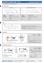
code ST02 | project A71 | release B ^ OUTPUT SIGNALS * The maximum frequency is guaranteed with a cable length up to 4 m. Serial output nxoxxoxaxoj: In case of cable extension, it is necessary to guarantee: • the electrical connection between the body of the connectors and the cables shield; • a minimum power supply voltage of 5 V to the sensor. s = thickness without double-sided tape. Thickness with double-sided tape + 0.1 mm. d = distance to be maintained between sensor and surface of the magnetic band (or eventual cover). ALIGNMENT TOLERANCES d 1 = distance to be maintained between sensor...
Open the catalog to page 2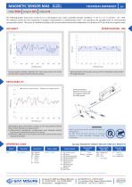
code ST02 project A71 release B The following graphs show tests carried out in a metrological room under controlled climatic conditions: T= 20 °C ± 0.1 °C and R.H.= 45 4- 55%. The reference system for the comparison of position measurements is interferometric with 1 nm resolution and equipped with an environmental compensation device. The sensor is installed according to the recommended mechanical configuration at a distance of 0.5 mm from the magnetic band. Accuracy graph: deviation between the value measured by the sensor and the value measured by the reference system. SDE (sub-division error)...
Open the catalog to page 3
GIVI MISURG Measuring and control systems Our branches in China, India and Turkey are completely independent in providing a before and after sales service and a fast and qualified technical assistance. DISTRIBUTORS AND SERVICE CENTERS AROUND THE WORLD • ARGENTINA • CZECH REPUBLIC • GREAT BRITAIN • SOUTH AFRICA • SOUTH KOREA Optical scales Magnetic systems Rotary encoders Digital readouts GIVI MISURE S.r.l. A SOCIO UNICO Via Assunta, 57 - 20834 Nova Milanese (MB) - Italy Tel.: +39 0362 366126 - Fax: +39 0362 366876 www.givimisure.it - [email protected] Applications CNC machines Press brakes Traditional...
Open the catalog to page 4All GIVI MISURE catalogs and technical brochures
 ST02
2 Pages
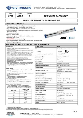 ST08
2 Pages
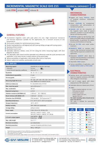 ST04
2 Pages
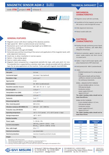 ST06
4 Pages
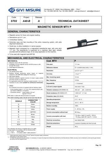 A40-B
2 Pages
 BROCHURE GVS 202 S
4 Pages
 BROCHURE MAGNETIC SYSTEMS
4 Pages
 BROCHURE GVS 600-608
4 Pages
 BROCHURE GVS 900 SERIES
4 Pages
 GENERAL CATALOG 2026
19 Pages
 GVS 508
4 Pages
 GVS 808
4 Pages
Archived catalogs
 THESI 320
2 Pages
 THESI 310
2 Pages
 VI518
2 Pages
 GVS
6 Pages
 AGS
2 Pages
 AGM
2 Pages
 AEN58
2 Pages
 VISION 518
2 Pages
 VISION 900
5 Pages
 MAGNETIC SENSOR MTV P
2 Pages
 REMOTE BOARD RB900
2 Pages
 GENERAL CATALOGUE
84 Pages
 GVS 200
6 Pages
 MTT-MTB
2 Pages
 VI900
2 Pages
 GVS 204
6 Pages


- GIVI MISURE incremental encoder
- Incremental rotary encoder
- Digital indicator
- Absolute rotary encoder
- Panel panel meter
- Solid-shaft rotary encoder
- Optical rotary encoder
- Hollow-shaft rotary encoder
- HMI
- HMI with touch screen
- IP65 rotary encoder
- Compact rotary encoder
- IP67 rotary encoder
- Aluminum rotary encoder
- DC rotary encoder
- LCD HMI
- GIVI MISURE linear encoder
- Flange rotary encoder
- Position indicator