- Catalogs
- Gie-Tec GmbH
- CNC RACK
CNC RACK
1 /21Pages

CNC RACK
1 /21Pages
Catalog excerpts

3 axis CNC Flat Table Machine Gie-Tec GmbH l der Schlierbach 18 An 3 axis CNC base machine Strong aluminum/steel construction Stepper controller integrated
Open the catalog to page 1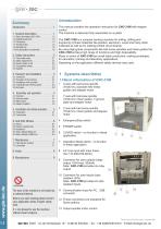
Summary Introduction . . . . . . . . . . . . . . . . . . . . 1 1. Systeme describtion. . . . . . . . . . . . 1 1.1 Basic information CNC-3100 . . . . . . . . . . 1.2 1.2 Operating elements . . . . . . . . . . . . . . . . . 1.3 1.3 Connectors . . . . . . . . . . . . . . . . . . . . . . . . 1.4 1.4 Technical data . . . . . . . . . . . . . . . . . . . . . 1.5 1.5 Intended use . . . . . . . . . . . . . . . . . . . . . . 1.5 1.6 EG declaration of conformity . . . . . . . . . . 1.6 2. Safety instructions . . . . . . . . . . . . . 2 2.1 Used safety signs . . . . . . . . . . . . . . . . . . 2.2 Safety...
Open the catalog to page 2
1.2 Operating elements of CNC-3100 Emergency-Stop Pushing the Emergency-Stop switch (4), the power supply of the stepper amplifier will be switched OFF immediately. At the same time the AC-output will be switched OFF. By this all motors of the CNC-3100 will be deactivated. For unlock the Emergency-Stop switch please turn button according directional arrow. To switch ON the motor amplifiers you have to push POWER key, aditional. POWER switch The POWER switch (5) will be used for switching ON the power supply of the stepper amplifier. Power switch only have function if - Emergency-Stop switch is...
Open the catalog to page 3
1.3 Connectors of CNC-3100 This chapter descripes all connectors of all devices which are used at this CNC-machine. AnalogGnd (Option) not connected not connected GndSpindle (Gnd) Gnd Vs (+24V PowSpindle (+24V) Spindle (15 pin D-shell connector, female) AnalogOut (Option) not connected not connected Vs (+24V) Overlaod StatusSpindle StartSpindle Gnd StatusSpindle This feature is not available at this time. Overload This feature is not available at this time-PowSpindle, GndSpindle The outputs „PowSpindle“ (+24V) und „GndSpindle“ will be used to switch ON the power relays inside the frequency converter FC...
Open the catalog to page 4
1.3.1 Connectors of CNC-3100 USB Interface (USB-A, female) USB-A connector for adapt the stepper control box to USB interface of the control PC. Please use a standard USB cable, shielded, wiring 1:1, male - male Moving range X/Y/Z Mounting area WxD Passage Z axis Travel speed Repeating accuracy Spindle pitch X/Y/Z Drive motors Positioning controller Overall dimension Weight 200x270x70mm 250x450mm 60mm 80mm/sec +/- 0.02mm 4/4/4mm 2-phase stepper motors Stepper motor controller with USB interface Micro-step operation (up to 25.000 steps/rev.) modular amplifiers 44V/4Amp CNC real-time operating...
Open the catalog to page 5
gie - tec 1.5 Intended use (Continuation) Before using the machine in any new application you have to make a new analysis of risk to get information about danger. Don´t start working the machine unless you have add the required safety equipment. The legal accident prevention regulations has to observed. The standard operation procedure of the operator has to abserved The ambient temperature of the machine has to be between - 5°C and +30°C. 1.6 EC Declaration of Conformity EC Declaration of Conformity in accordance with Low Voltage Directive 2006/95/EG in accordance with EMC Directive 2004/108/EG...
Open the catalog to page 6
2. Safety instructions 2.1 Used safety signs This sign will point a general information such as information about handling or experience. This will help you understanding the machine and the behavior of it. This symbol indicates danger that cause damages for person's health, physical injury or death. Warning of danger from electrical voltages. Ignoring can lead ro serious injury or death. This sign points to important notes. Ignoring this symbol leads to damages of the machinery or parts of it. Damages like that may results by wrong handling. In that case guarantee items are excluded. 2.2 Safety...
Open the catalog to page 7
2.3 General types of risk The control unit of the machine needs a main voltage between AC110-250/50-60HZ The motor output voltage is about 40V (pulsed voltage). The ouput voltage of AC output is at the same high then the AC input voltage. Touching components which are connected to voltage may cause severe injury. By this following precuations are necessary • Don't touch to any energized components • Report defects on cables and wires immediately maintenance stuff • Maintenance and repair only have to be operate by trained maintenance stuff. • Repair of the motor control unit only have to be done...
Open the catalog to page 8
Technische Änderungen vorbehalten Gie-Tec GmbH
Open the catalog to page 9
When planning the floor space for the CNC machine regard the universal access for instruction personnel during a maintenance resp. service phase! The space requirement of the machine is limited to the external measurements and to sufficient room in front of the machine in order to operate and arrange the processing, plus approx. 10 cm behind the machine to allow for connectors. The hood of the housing opens upwards. Thus, the required total height is approx. 1,0m 3.2 Transport of the CNC machine DANGER! Unplug the power cable before each transport. Remove transport lock from the frame feeds....
Open the catalog to page 10
gie - tec 3.4 Coordinate system and reference point The coordinate system of the machine is determined as shown in figure. However, you can displace the P0 work piece zero point freely via software it. Ex works the home position of the machine (machine origing) is defaulted to the back (Y axis) and left side (X axis) and t the top (Z-axis). Labels on the machine mark the axes. You are not allowed to put a CNC market CNC machine into operation if the enclosure is not complete, intact or the panes damaged. The transparent panes (material,: acrylic, ploycarbonate) mounted in the machine frame resp....
Open the catalog to page 11
4 Assembly and operation 4.1 Motor control unit The stepper control unit of the CNC-3100 is integrated in the backside enclosure of the machine. There you'll find following components: - Interfaceboard with connectors for the stepper power stages, DC/DC converters, connectors for user inputs/outputs, connector for USB/LPT converter - Relay board with the safety relays - Power stages for the steppers The main power supply is mounted below the mounting plate of the CNC DC/DC converter! Power stages for 2-phase stepper (type: SMCI35) USB/LPT converter (optional) D-shell connector 25 pin, male for adapting...
Open the catalog to page 12All Gie-Tec GmbH catalogs and technical brochures
 CNC-PUREXL-LIN
2 Pages
 UV-EXPOSURE BOXES
4 Pages
 UV-Exposure Box
4 Pages

- Sanxing Electric machining center
- Rectangular housing
- 3-axis CNC milling center
- Profile
- Metal housing
- Metal profile
- Electronic housing
- Custom housing
- Compact housing
- Modular housing
- Heater
- Aluminum CNC milling center
- Desktop housing
- Manual shear
- Manufacturing enclosure
- Extruded aluminum enclosure
- Electric heater
- Printed circuit board enclosure
- Anodized aluminum profile
- Extruded enclosure