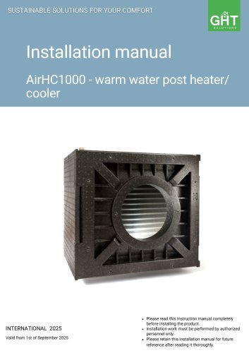
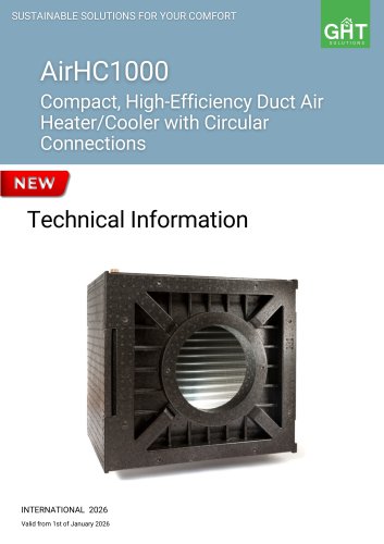
- Catalogs
- GHT Solutions Ltd
- Geothermal pre-preconditioning

Geothermal pre-preconditioning

Geothermal pre-preconditioning
This document serves as an installation manual for the Geothermal Pre-Preconditioning Brine Defroster models G-2000, G-4000, G-6000, G-8000, and their variants. It provides comprehensive instructions for authorized personnel on installation, operation, and maintenance.
The warranty covers defects in materials or construction for two years from delivery. Unauthorized modifications, use of non-original parts, or maintenance by unauthorized personnel voids the warranty.
The brine defroster is designed for frost protection in ventilation units, heating intake air in winter and cooling it in summer using a brine-driven geothermal heat collector. It includes a G4 filter and can be configured for left or right airflow.
Installation must adhere to local building and safety regulations, performed only by authorized personnel. The brine circuit is pressurized, requiring pressure release during maintenance. The unit is for comfort ventilation systems only.
Adequate space for air duct connections and maintenance is necessary. The unit should be in a frost-protected room, and the liquid must not freeze. An intake air isolation damper is needed for temperatures below -15°C.
The package includes the brine defroster unit with an integrated G4 filter, a wall mounting bracket, an installation manual, and rubber spacers.
Mount the unit on a wall using the provided bracket, ensuring the wall supports the weight. Connect air ducts with airtight seals. Drain condensate using a siphon.
Install the geothermal heat collector according to soil type and local conditions. Insulate and steam-tighten brine pipes. The circuit should be lockable, fillable, and drainable individually.
The brine defroster is controlled externally, with the temperature sensor placed as per the control manual.
Fill the system with an ethylene glycol-water mixture, ensuring the correct concentration. Follow detailed steps for filling and adjusting the brine pump.
The brine defroster uses a brine pump to circulate an ethylene glycol-water mixture. Flow rates vary by model: 6-7 l/min for G-2000/G-2001, 9-10 l/min for G-4000/G-4001, 21 l/min for G-6000/G-6001, and 36 l/min for G-8000/G-8001. Valve X0 is open when parallel to the pipe and closed when perpendicular. Filling valves X1 and X2 are for filling operations. A vent valve is required at the highest point.
Operation: The pump operates at 220 V with specific wiring instructions. LED indicators show operational status and faults.
Maintenance: Regular maintenance includes filter replacement every six months, cleaning the condensate drain every three months, and annual hydraulic circuit inspection. Only authorized personnel should refill or maintain the system.
Filling Instructions: Detailed steps for refilling the system, including pressure settings and glycol percentage checks.
End-user tasks: Filter replacement, condensate drain cleaning, and pressure checking.
Professional tasks: Inspection and cleaning of components, replacement of parts like the brine pump, expansion tank, and pressure gauge.
Common issues include incorrect pump settings, clogged filters, and blocked heat exchangers. Solutions involve checking system pressure, replacing filters, and cleaning components. Noise issues may indicate air gaps or siphon problems, requiring sealing or filling actions.
The installation sketch outlines the connection of the brine defroster to the ground collector and other components like the heat recovery ventilation unit and expansion vessel.
For further assistance, contact "GHT SOLUTIONS" Ltd, located in Valletta, Malta.
Catalog excerpts

SUSTAINABLE SOLUTIONS FOR YOUR COMFORT ^ Valid from 1st of September 2025 G-2000, G-4000, G-6000, G-8000/ G-2001, G-4001, G-6001, G-8001 Please read this instruction manual completely before installing the product. Installation work must be performed by authorized personnel only. Please retain this installation manual for future reference after reading it thoroughly.
Open the catalog to page 1
Safety Precautions Thank you for purchasing brine defroster G-2000/G-4000/G-6000/G-8000, G-2001/G-4001/G-6001/G-8001 series. READ THESE INSTRUCTIONS CAREFULLY BEFORE INSTALLING AND USING THE EQUIPMENT! THIS INSTRUCTION HAS BEEN MADE WITH THE GREATEST CARE. HOWEVER, THIS INSTRUCTION CONFERS NO RIGHTS. WE RESERVE THE RIGHT TO CHANGE ALL OR PART OF THE CONTENTS OF THIS INSTRUCTION WITHOUT PRIOR NOTICE. This instruction contains all information necessary for an optimal installation and startup by skilled personnel. It can also be used as a manual for maintenance and service work. It is absolutely...
Open the catalog to page 2
• after the warranty period has elapsed; • the unit is used without genuine filters; • parts are used, that have not been delivered by the manufacturer; • the unit is used improperly; • defects occur due to improper connection or use and decontamination of the system; • non-authorized modifications are made. The brine defroster has been developed and produced for use in so called comfort ventilation systems. Any other use is considered an improper use and can lead to damages to equipment and persons; the manufacturer is not liable in such cases. The manufacturer is not liable for any damages...
Open the catalog to page 3
• The following equipment has to be provided: - air duct connections. - mains supply 230 VAC (for control module). - appliances for condensate drain. - liquid tubes of the duct work. • The brine defroster has to be installed in a frost-protected room. The liquid inside the system must not freeze. Freezing of the liquid would damage the system irreparably. • The condensate has to be drained off unit. Use a siphon to drain off the condensate. • We recommend not to install the brine defroster in rooms with high humidity (e.g. bathroom/toilet). Thereby, • condensate formation on the outside of the...
Open the catalog to page 4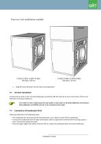
2. Hang the brine defroster into the wall mounting bracket. Connect the air ducts to the corresponding pipe connections DN 250. Seal all air duct connections of the brine defroster ensuring air tightness. The intake air duct, beginning from wall, gable or base plate to the brine defroster and between brine defroster and MVHR-unit has to be insulated steam-tight 5.3 Connection of Condensate Drain Please pay attention to the following notes: • The condensate has to be drained off frost-protected. Use a siphon to drain off the condensate. • Connect the condensate drain air-tight to the siphon (with...
Open the catalog to page 5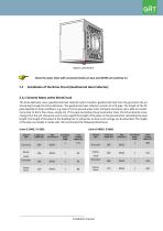
Check the water drain with connected intake air duct and MVHR unit switched on. The brine defroster uses a geothermal heat collector which transfers geothermal heat from the ground to the air streaming through the brine-defroster. The geothermal heat collector consists of a PE-pipe. The length of the PE pipe depends on local conditions, e.g. type of soil or ground water level. Compact and loamy soil is able to transfer more heat to brine than loose, sandy soil. If the pipe lays below the ground water level, the brine absorbs more energy from the soil. Please be sure to only regard the length...
Open the catalog to page 6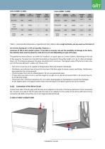
Table 1: recommended dimensions of geothermal heat collector As a rough estimate, you can work on the basis of 0.5 m brine ducting per 1 m3/h air quantity. However, a minimum of 100 m with smaller system. To be able to securely rule out the possibility of damage to the ducts, the collector ducts must be placed in a bed of 0.4 m of sand (depending on type of PE pipe). The geothermal heat collector can either be installed in an open space or a trench system, depending on the size of the property. The pipe has to be laid horizontally in the ground, the perfect depth is 1,5 to 2 m (but not deeper...
Open the catalog to page 7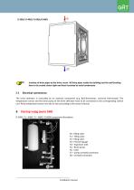
Insulate all brine pipes of the brine circuit. All brine pipes inside the building and the wall bushing have to be sealed steam-tight and heat-insulated to avoid condensate. Electrical connections The brine defroster is controlled by an external component (e.g. BUS-thermostat, universal thermostat). The temperature sensor and the brine pump of the brine defroster have to be connected to the corresponding control unit. Place temperature sensor into the air duct according to the control manual. Startup vajag jaunu bildi X0 - filling valve X1 – filling valve X2 - filling valve X3 - Pressure gauge...
Open the catalog to page 8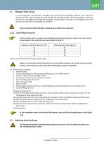
Filling the Brine Circuit 6.1.1 In normal operation, the defroster's valve X0 is open and the filling valves X1 and X2 are closed. The brine defroster is filled using the filling valves X1 and X2. The valve X0 is open when the handgrip is parallel to the pipe. The valve X0 is closed when the handgrip is perpendicular to the pipe. On the highest point of the system vent valve has to be installed (by customer). Only an authorized fitter/plumber is allowed to (re-)fill the brine-defroster. Initial Filling Instruction Fill the system with a ready-to-use ethylene glycol-water mixture. Please note...
Open the catalog to page 9
220 V cable black/brown: LI, l~230V/50Hz blue: Neutral N yellow/ green: Earth conductor Variable differential pressure j j j Constant differential pressure Pump operating button Indicator lights (LEDs) Signal display • LED is lit up in green in normal operation • LED lights up/flashes in case of a fault • Select control mode • Select pump curve (I, II, III) within the control mode Press and hold • Activate the pump venting function (press for 3 seconds) • Activate manual restart (press for 5 seconds) • Lock/unlock button (press for 8 seconds) The brine defroster utilizes a brine pump to pump...
Open the catalog to page 10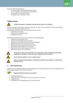
The pump adjustment depends on: • the overall length of the geothermal heat collector; • the inner diameter of the geothermal heat collector; • the composition of the liquid mixture; • the temperature of the liquid mixture. Periodic maintenance is absolutely necessary for the system to run properly. To assure a trouble-free operation of the brine defroster over years, we recommend to conclude a maintenance contract with a specialized maintenance firm. The following maintenance work can be carried out by the end user: • Cleaning of the condensate drain; The following maintenance work has to be...
Open the catalog to page 11All GHT Solutions Ltd catalogs and technical brochures
 Technical Information
16 Pages
 Technical Information
16 Pages