Moulded case circuit breaker

Moulded case circuit breaker
Catalog excerpts

Series G Moulded Case Circuit Breakers Product Guide • Up to 690 Vac • 18kA to 100kA Icu • 16-2500 Amperes • IEC 60947-2 Safety, Reliability and Performance verified with the KEMA KEUR mark
Open the catalog to page 1
July 2004 Moulded Case Circuit Breakers 1 16 – 2500 Amperes for IEC Applications Series G Frame Sizes GE through GR (16 – 2500 Amperes) Description Page Standards . . . . . . . . . . . . . . . . 1 General Information . . . . . . . . 1 Electrical Characteristics . . . . 2 Multi-Function Electronic Trip Units . . . . . . . 8 Electronic Trip Unit Selection Guide . . . . . . . . . . 9 Frame Size Selection Guide & Ordering Information/ Termination Accessories GE-Frame, 16 – 160 Amperes . . . . . . 11 GJ-Frame, 20 – 250 Amperes . . . . . . 13 GL-Frame, 100 – 630 Amperes . . . . . 15 GN-Frame, 400 –...
Open the catalog to page 2
July 2004 Moulded Case Circuit Breakers 3 16– 2500 Amperes for IEC Applications Series G Frame Sizes GN and GR Table 1. Electrical Characteristics (Continued) 3 Not suitable for dc application. 4-pole earth fault not available. n Available — Not Available Frame size and page number GN (p. 17) GR (p. 21) Maximum Rated Current (Amperes) 800, 1250 1600 1600, 2000, 2500 Breaker Type S H C S H C Number of Poles 3, 4 3, 4 3, 4 Breaking Capacity (kA rms) ac 50 – 60 Hz IEC 60947-2 220 – 240 Vac Icu 85 100 200 85 135 200 Ics 85 100 100 85 100 100 380 – 415 Vac Icu 50 70 100 50 70 100 Ics 50 50 50 50 50...
Open the catalog to page 4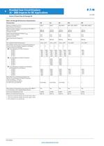
July 2004 4 Moulded Case Circuit Breakers 16 – 2500 Amperes for IEC Applications Series G Frame Sizes GE through GR Table 2. GE through GR Electrical Characteristics 1 Thermal overload release set to the lower value. 2 Thermal overload release set to the upper value. 3 Not suitable for dc switching. Technical Data GE GJ GL GN GR Maximum Rated Current In Depending on the Version 160 A 250 A 400, 630 A 800, 1250, 1600 A 1600, 2000, 2500 A Rated Insulation Voltage U, According to IEC 60947-2 Main Conducting Paths Auxiliary Circuits 690 Vac 690 Vac 750 Vac 690 Vac 750 Vac 690 Vac 750 Vac 690 Vac...
Open the catalog to page 5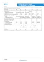
July 2004 Moulded Case Circuit Breakers 5 16 – 2500 Amperes for IEC Applications Series G Frame Sizes GE through GR Table 2. GE through GR Electrical Characteristics (Continued) Technical Data GE GJ GL GN GR Conductor Cross Sections and Terminal Types for Main Conductors n Solid or Stranded n Finely Stranded with End Sleeve n Bus Bar Tightening Torque for Box Terminals Tightening Torque for Bus Bar Connection Pieces Box Terminals 2.5 to 70 mm 2 2.5 to 50/70 mm 2 — 5.6 Nm 5.6 Nm Box Terminals 50 to 150 mm 2 35 to 120 mm 2 — 20 Nm 15 Nm Box Terminals 95 to 240 mm 2 70 to 150 mm 2 — 42 Nm 30 Nm...
Open the catalog to page 6
July 2004 6 Moulded Case Circuit Breakers 16 – 2500 Amperes for IEC Applications Series G Frame Sizes GE through GR Table 2. GE through GR Electrical Characteristics (Continued) Technical Data GE GJ GL GN GR Auxiliary Switches Rated Thermal Current lth Rated Making Capacity 6 A 20 A 6 A 20 A 6 A 20 A 6 A 20 A 6 A 20 A ac (ac-15) n Rated Operational Voltage n Rated Operational Current 230/400/600 V 6/3/0.25 A 230/400/600 V 6/3/0.25 A 230/400/600 V 6/3/0.25 A 600 V 6 A 600 V 6 A dc (dc-13) n Rated Operational Voltage n Rated Operational Current 125/250 V 0.5/0.25 A 125/250 V 0.5/0.15 A 125/250...
Open the catalog to page 7
July 2004 Moulded Case Circuit Breakers 7 16 – 2500 Amperes for IEC Applications Series G Frame Sizes GE through GL dc Switching Duty The GE- to GL-Frame circuit breakers are also suitable for switching dc currents. The GN- and GR-Frame circuit breakers are not suitable for dc currents due to the solid-state overcurrent release system. For switching dc currents, however, the maximum permissible dc voltage per conducting path has to be considered. For voltages higher than 250 volts, the series connection of two or three conducting paths is required. As the current has to flow through all conducting...
Open the catalog to page 8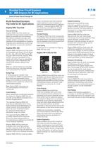
July 2004 8 Moulded Case Circuit Breakers 16 – 2500 Amperes for IEC Applications Series G Frame Sizes GJ through GR Multi-Function Electronic Trip Units for All Applications Digitrip RMS Trip Units True rms Sensing Digitrip RMS Trip Units utilise our patented microprocessor-based intelligence to provide true rms sensing, permitting increased accuracy and reliable system protection. True rms sensing is not susceptible to nuisance tripping when waveforms containing high harmonic currents are present. Digitrip RMS 310 Digitrip RMS 310 Electronic Trip Units are available with Eaton Circuit Breakers...
Open the catalog to page 9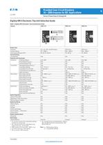
July 2004 Moulded Case Circuit Breakers 9 16 – 2500 Amperes for IEC Applications Series G Frame Sizes GJ through GR Digitrip RMS Electronic Trip Unit Selection Guide Table 4. Digitrip RMS Electronic Trip Unit Selection Guide 1 GJ- and GL-Frames have selectable settings instead of a rating plug. 2 GJ- and GL-Frames have adjustable long delay times of 2 – 24 seconds. 3 2500 ampere GR-Frame 200 – 600% x (In). 4 GJ-Frame also has a 14X setting. 5 Not to exceed 1250 amperes. 6 GJ- and GL-Frames are Instantaneous, 120 ms. GN- and GR-Frames are Instantaneous, 100, 300 and 500 ms. Note: In = Rating plug...
Open the catalog to page 10
July 2004 10 Moulded Case Circuit Breakers 16 – 2500 Amperes for IEC Applications PG0120002U www.eatonelectrical.com
Open the catalog to page 11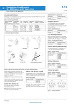
July 2004 12 Moulded Case Circuit Breakers 16 – 2500 Amperes for IEC Applications Series G Frame Size GE, 160 Amperes Line and Load Terminals GE-Frame circuit breakers and moulded case switches have 3T125EF line and load terminals as standard equipment. Table 7. Line and Load Terminals 1 Standard line and load terminals included with GE-Frame MCCBs. 2 3 terminals with terminal shield. 3 4 terminals with terminal shield. Figure 2. Line and Load Terminals, End Cap Kits and Control Wire Terminal Kit Insert collar enclosing conductor as shown in Figure 2. Locate nut on top of conductor and tighten...
Open the catalog to page 13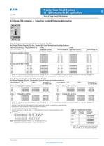
Moulded Case Circuit Breakers 13 July 2004 16 – 2500 Amperes for IEC Applications Series G Frame Size GJ, 250 Amperes GJ-Frame, 250 Amperes — Selection Guide & Ordering Information Table 15. Complete Circuit Breaker with Thermal-Magnetic Trip Unit — Incl. Frame, Thermal-Magnetic Trip Unit, Standard Box Clamp Terminals and Mounting Hardware 1 1 Suffix “G” represents box clamp type terminals. Change “G” to “M” for screw/keeper nut type termination suitable for cable lug. See page 14. 2 Neutral protection is indicated by the fourth character: 4 = 0%, 8 = adjustable 0 or 60% and 9 = 0 or 100%. Table...
Open the catalog to page 14All GHISALBA catalogs and technical brochures
 INVERTER TYPE VFD-C VFD-CP
2 Pages
 Temperature control
6 Pages
 SWITCH DISCONNECTOR
4 Pages
 Push button
18 Pages
 modular contactor
6 Pages
 Manual Motor Starters
5 Pages
 auxiliary contactor
1 Page
 mini-contacteur
10 Pages
Archived catalogs
 PanelMate, series Pro 1100
2 Pages
 PanelMate
15 Pages
 Inverter and soft starters
18 Pages
 Motor control overview
4 Pages
 HMI products
4 Pages
 Mini-contactors
8 Pages
 Contactors GH15 & GH
42 Pages
 GHA Manual Motor Starter
8 Pages
 PanelMate, series ePro PS
2 Pages
 Converters AC/DC
6 Pages
 CONTACTORS
2 Pages
 CM
CM27 Pages
 PanelMate, software for ePro
8 Pages


- Power supply unit
- DC power supply
- AC/DC power supply
- Push-button switch
- Technology switch
- Protection relay
- Multipole switch
- Programmable logic controller
- DIN rail power supply
- Electromechanical switch
- Time relay
- Rotary electric switch
- Contactor
- Frequency inverter
- Touch push-button switch
- Touch switch
- Technology push-button switch
- Fieldbus PLC
- Electromechanical push-button switch
- Illuminated switch