
Catalog excerpts

GfG Gesellschaft für Gerätebau mbH Klönnestraße 99 – D-44143 Dortmund Phone +49-(0)231-56400 0 Fax +49-(0)231-516313 E-Mail info@gfg.biz Internet www.gfg.biz MICRO IV Dockingstation DS220 Shortform Manual – Function Test Application Connections and Operational Elements On / Off Switching between Bump Test/Calibration The docking station DS220 is an automatic test station for calibration and bump test of the personal gas monitor MICRO IV. Positioning / Mounting The docking station must be placed on a fix and plane surface. Make sure that the test gas is discharged freely and without pressure! Zero gas Test gas In In Test gas supply must be effected without pressure by means of the pump inside the docking station. Gas outlet Connection for pressure switch 12 V DC Mains supply COM port RS485 for PC (USB) resp. combination of several docking stations MMC Card Operation Push the green switch to turn the docking station on or off. Flashing of the green On/Off switch indicates that the required pressure from the test gas bottle is too low (test gas used up). The docking station may be equipped with up to 6 detectors simultaneously. The bump test starts automatically. Bump test or calibration can only be done for MICRO IV detectors for the same gas and detection range. For detectors monitoring a different gas or detection range you have to supply different test gas, and the docking station has to be set for new parameters by means of the configuration software. Before starting the test push the red button to select between bump test or calibration. Should the red button be lit, calibration is effected – otherwise a bump test is done. When you put a detector in the docking station, the status LED for the relevant slot flashes yellow for approx. 10 seconds. During this time you may put additional detectors into the docking station. As soon as a status LED turns to „permanent yellow light“, the test is started and you cannot place additional detectors, as these would not be recognized. The test results are signalized visually by flashing or lighting of the relevant status LED. Functions of status LEDs LED flashing yellow = Test preparation LED permanent yellow = Start of detector test LED flashing red = Gas flow failure LED permanent red = Test failed LED permanent green = Test completed, detector o.k. Once the test is completed (green LED), you should remove the detectors immediately. Should the red LED light up, repeat the test. All information about the bump test and calibration of the individual detectors are stored on a MMC (if fit) and can be transferred to a PC by means of a card reader. Data transfer to a PC is effected automatically, if a MMC is fit and if the docking station is connected to a PC. The bump test includes: Setting of time Check of buzzer Visual check / Alarm LED Response time of sensor, response sensitivity Detector fault Setting of interval for next bump test, e.g. 14 days
Open the catalog to page 1All GfG - Gesellschaft für Gerätebau catalogs and technical brochures
-
 MiniCal III
4 Pages
-
 The leak detector G300 II
1 Pages
-
 Smart Pump G400-MP2
12 Pages
-
 Microtector II G450
4 Pages
-
 Drop-in charger
15 Pages
-
 Dockingstation DS404
17 Pages
-
 Smart Pump G400-MP2
2 Pages
-
 EC22
EC222 Pages
-
 ZD22
ZD222 Pages
-
 IR22
IR222 Pages
-
 CS22
CS222 Pages
-
 CC28DA
2 Pages
-
 CC28D
CC28D2 Pages
-
 EC28i
EC28i2 Pages
-
 EC28Di
2 Pages
-
 EC28DB
2 Pages
-
 EC28DAR
2 Pages
-
 EC28DAB
2 Pages
-
 EC28DA
2 Pages
-
 EC28D
EC28D2 Pages
-
 EC28B
EC28B2 Pages
-
 CI21
CI212 Pages
-
 CS21_Flammable
2 Pages
-
 CS21_Refrigerant
2 Pages
-
 GMA200 MGSS
4 Pages
-
 MiniCall III
2 Pages
-
 MiniCal Refrigerant System
4 Pages
-
 Transmitter EC24
2 Pages
-
 Transmitter CC28
2 Pages
-
 Transmitter IR29
4 Pages
-
 9025-XPS
2 Pages
-
 GMA200-MGSS
2 Pages
-
 G300 III
2 Pages
-
 EC28
EC282 Pages
-
 CS21
CS212 Pages
-
 Micro III
2 Pages
-
 GMA81/ GMA81 A
1 Pages
-
 Controller GMA200-MT
4 Pages
-
 Controller GMA200-MW
4 Pages
-
 GMA313
2 Pages
-
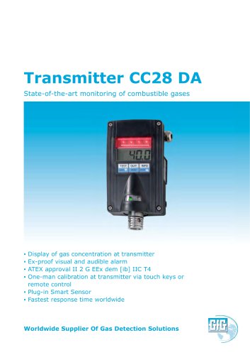 Transmitter CC28 DA
2 Pages
-
 Transmitter CC28 D
2 Pages
-
 Transmitter ZD21
2 Pages
-
 Transmitter IR24
4 Pages
-
 Dockingstation DS400
2 Pages
-
 GfG Products & services Brochure
15 Pages
-
 Microtector II G450 Brochure
4 Pages
-
 Transmitter CC28 Brochure
2 Pages
-
 GMA36 Pro Brochure
2 Pages
-
 GMA 40 Series Broschure
2 Pages
-
 Transmitter EC24
2 Pages
-
 GMA80/81/84/88 Brochure
4 Pages


Archived catalogs
-
 Test gases
2 Pages
-
 MICRO Motorised pump
2 Pages
-
 GMA101/103/104
4 Pages
