
- Catalogs
- GFC AntriebsSysteme GmbH
- Product catalogue 2012

Product catalogue 2012

Product catalogue 2012
This catalog from GFC AntriebsSysteme GmbH provides an overview of their high torque precision products, including worm gear units and helical-worm gear units. It emphasizes the company's commitment to quality and innovation, supported by certifications like EN ISO 9001 and EN ISO 14001.
The catalog lists various gear units and motors, specifying center distances and customization options. It highlights the importance of precise sizing and provides a detailed list of specifications required for inquiries, such as purpose, power, torque, and environmental conditions.
Efficiency ratings for worm gearboxes are discussed, noting that they depend on factors like running speed and surface quality. The document explains static and dynamic self-locking effects and advises consulting GFC for specific requirements.
Selection is based on mechanical and thermal wear, with calculations provided for required torque. Factors influencing selection include operation mode, start frequency, ambient temperature, and lubricant type. Tables are provided to assist in determining these factors.
Installation guidelines and permissible loads are outlined, emphasizing the importance of proper lubrication and running conditions. The catalog advises on selecting gearboxes based on actuator torque and provides factors for different operating conditions.
GFC offers a wide range of customizable drive solutions, supported by a knowledgeable field service team. The catalog serves as a comprehensive guide for selecting and specifying gear units and motors for various applications.
The document provides detailed technical data for worm gear units, specifically focusing on sizes S 40.1 to S 160.1. It includes power tables for different sizes, indicating driving power, rated speeds, output torques, operating efficiency, and gear ratios. The data is presented for two different input speeds: 250 1/min and 1400 1/min.
The tables highlight the maximum output torques that can be reached under momentary load conditions but should not be exceeded. The efficiency percentages vary with different gear ratios and input speeds.
Information on radial forces is provided for different sizes, indicating the permissible forces at a rated speed of 1400 1/min. The document notes that axial forces can absorb up to 50% of the permissible radial forces.
The document lists the masses and lubricant quantities for different service positions and sizes, indicating the basic version and attachment parts. It specifies the lubricant quantities in liters and the corresponding weights in kilograms.
Guidelines for mounting and assembly of attachable gearbox motors are provided, emphasizing the importance of proper torque support to minimize bending wear on the work machine shaft. The document also includes recommendations for handling attachable gearboxes after prolonged use to prevent difficulties due to environmental influences.
Detailed dimension sheets are included for sizes SV 200.1 to 315.1, specifying input and output dimensions, gear ratios, and possible mounting positions for torque converter bearings. The document also provides application guidelines for the attachment of torque supports.
The document discusses the combination of worm gear units with helical gear units to achieve higher transmission ranges and low-noise operation. It highlights the benefits of compact drive design, high efficiency, and cost reduction. Various types of helical-worm gear units are listed, including gear motor units and those with different shaft configurations.
Instructions for the position of ventilation, oil filling, terminal box, and cable inlets are provided, with standard positions indicated for different service positions.
The document provides detailed technical data for helical-worm gear units from the GFC Product Catalog 2012. It includes specifications for various sizes and outlines parameters such as driving power, rated speeds, output torques, operating efficiency, and gear ratios. The document emphasizes that maximum output torques may be reached often in momentary loads but should not be exceeded.
The power tables for sizes SS 160 and SS 250 provide detailed data on gear ratios, output torques, and rated speeds for different configurations. These tables are crucial for selecting the appropriate gear unit based on specific operational requirements.
The document discusses the absorption of axial forces up to 50% of the permissible limit and provides data on radial forces for different sizes and configurations. This information is essential for ensuring the durability and reliability of the gear units under various load conditions.
Guidelines for the installation of attachable worm gearboxes are provided, emphasizing the importance of axial attachment on the work machine shaft and the use of elastic sockets to dampen torque impacts. Recommendations for preventing tribo-corrosion and facilitating the removal of gearboxes after prolonged use are also included.
The document outlines the application of torque supports in gearboxes, detailing the forces exerted on the work machine shaft and the importance of minimizing bending wear. It provides guidance on the appropriate selection of force-exertion points and the direction of exterior forces.
The GFC "whisper gear" is highlighted for its low noise level of less than 55 dB(A) under load, achieved through the use of worm gear stages and helical precision spur gears. This feature is particularly beneficial in stage engineering applications where noise reduction is critical.
The document serves as a comprehensive guide for selecting, installing, and maintaining helical-worm gear units, with a focus on maximizing performance and reliability while minimizing noise and wear.
This document provides technical specifications and operational guidelines for various gear units and drive systems used in elevators and escalators, as well as solar tracker systems. It includes detailed information on components, options, and performance metrics.
- Double Brake and Incremental Transmitter: Includes options such as brake monitoring, handwheel, traction-sheave terminal, and transmitter cable. Operable at a maximum distance of 30 meters with a cable.
- Elevator Gear Boxes: Detailed technical data for sizes SS 80.1 to SS 250, including dimensions, weight, and performance metrics like speed and load capacity.
- Escalator Gear Units: Specifications for noise levels, lubrication, and radial forces. Gear units are designed to meet standards such as DIN 3990 and EN 115.
- Slewing Gear Units for Solar Trackers: Designed for high accuracy and efficiency, with specifications for dimensions and materials to ensure durability and corrosion resistance.
- Calculation of Traction Sheave Shaft: Includes formulas for axle load and safety factors, adhering to DIN 743 standards.
- Gearbox Selection: Provides a method for determining the appropriate gearbox size based on lifetime and torque requirements.
- For escalator gear units, maintain noise levels below 55 dB(A) and ensure continuous quality control.
- For solar tracker systems, use worm gear units for minimal backlash and high reliability.
- Technical data tables provide dimensions, weight, and performance metrics for various gear unit sizes.
- Graphs illustrate the relationship between equivalent output torque and lifetime, highlighting the efficiency and durability of the gear units.
This document is a technical catalog from GFC Product Catalog 2012, detailing specifications, guidelines, and operational data for slewing gear units and worm gear motors. It includes information on design, operation modes, ambient conditions, loads, sealing, efficiency, self-locking capacity, lubrication, and order processing.
The slewing gear units are designed for various operation modes, including continuous and intermittent duty. They can operate in ambient temperatures ranging from -20°C to +70°C. The permissible loads are specified in load diagrams, and the units are sealed with double-lipped seals made of hydrated nitrile rubber.
The document outlines several operation modes (S1 to S10), each with specific characteristics regarding load and speed changes. For example, S3 is periodic intermittent duty without start process influence, while S9 involves non-periodic load and speed changes.
The efficiency ratings are average values for well-run-in gearboxes. Self-locking capacity is discussed, differentiating between static and dynamic self-locking effects. The document advises against relying solely on self-locking for braking purposes.
Slewing gearboxes are pre-filled with grease and require regular re-greasing with compatible grease types. A table of recommended lubricants is provided.
Technical data includes torque values, mechanical wear selection, and permissible loads. Equations for calculating necessary torque and mechanical forces are provided.
Details required for processing orders include load specifications, mounting positions, ambient conditions, and additional options. Contact information for GFC AntriebsSysteme GmbH is provided.
GFC offers complete drive systems for solar thermal power stations, including worm gear motors with various configurations and options.
Worm gear motors are available with three-phase AC asynchronous motors, conforming to German and international standards. They feature protection class IP 55 and heat class F, with various voltage and frequency options.
Motors are designed for continuous operation under specific conditions, including coolant temperature and mounting height. Deviations from these conditions affect output values.
The motors are designed for continuous operation mode S1 according to VDE 0530. Other operation modes include S2 (short-time duty), S3 (intermittent duty), and S4 (continuous duty with intermittent loading). Ambient temperature range is -35°C to +40°C. Overload capability allows for 1.5-fold nominal current for 2 minutes and 1.6-fold nominal torque for 15 seconds.
Motors are cooled by radial fans made of synthetic material or aluminum-cast alloy, ensuring cooling regardless of rotation direction. Adequate space must be maintained for air intake.
Standard protection is IP 55 with heat class F. Options for higher protection up to IP 66, climate control, thermal winding protection, and explosion protection are available.
Brake motors indicate holding torque when idle. Various brake designs are available, including single and double-surface brakes. Brake spool voltage is configured to match motor-delta voltage, with options for rectifiers and custom voltages.
Motors include AC motors with squirrel cage rotors, pole-reversible motors, and modifications such as ex-protected motors, single-phase AC motors, and motors with external ventilation. Custom modifications are available upon request.
Data includes nominal output, speed, voltage, and current for various motor types. Motors are designed for operation mode S1, continuous operation, and protection class IP 55.
The document provides detailed technical specifications and benefits of the Milan drive advanced servo actuators, highlighting their compact design, high dynamics, and precise positioning capabilities. These actuators are suitable for various industrial applications, including textile, packaging, and medical engineering.
The Milan drive advanced features an AC-synchronized servo motor with optional holding brake and position-transmitter systems. It supports digital position and rotation output control, with a power supply of 230 V AC. The protection class is IP 64, with an optional upgrade to IP 67 for harsh environments. The servo actuators are available in three sizes, each with specific dimensions and weight.
These actuators are designed for high positioning accuracy and dynamic performance, suitable for use in textile machines, packaging machines, medical engineering, and more. They are also applicable in custom mechanical engineering and conveyance engineering.
The integrated controls of the Milan drive advanced simplify installation and maintenance. The device is ready to operate upon connection to the power supply and data line. It offers high functionality and flexibility, with simple integration into field bus systems and easy parameterization via the RS 232 interface.
The document includes detailed technical data such as nominal speed, power, torque, and electrical data for each size. It also covers the inputs and outputs, including digital and analog options, and the field bus interfaces available.
The document provides dimension sheets for both axial and angular designs, detailing the length, width, height, and weight for each model. It also specifies the motor flange dimensions and distances for electrical connections.
The Milan drive advanced servo actuators offer a robust solution for industries requiring precise and dynamic motion control. Their compact design, integrated controls, and adaptability to various applications make them a valuable asset in industrial automation.
The document outlines the specifications for the Milan drive advanced, including holding brake options, static holding-torque values, and brake management. It details the integration of the brake into program procedures and the availability of additional application-specific functions upon request.
Programming and parameterization of operation data records are conducted via a PC connected to the RS 232 interface. The document mentions the use of the MDAwin software for parameterization and the compatibility with Windows 2000/XP. It also discusses the storage and transfer of configuration data for Milan drive advanced actuators.
The document describes the use of Milan functional components based on Simatic software Step7 for quick commissioning of the Milan Servo actuator. It highlights the flexibility in application realization through the combination of various components.
Reference operation management can be initiated through various methods, including power application and external signals. Position control is managed internally via a P-controller, with adjustable control-parameter sets and position control hold time.
The document provides installation guidelines, including operation data record linking, manual operation mode, and customizable operation data records. It also covers single-step operation, procedure control, and Teach In capabilities.
Comprehensive monitoring functions and status signals are detailed, with differentiation between faults and warnings. The document includes examples of warnings and faults, event memory, and an operating hours counter.
Protection classes, corrosion protection, ambient temperatures, and explosion safety are discussed. The document affirms compliance with EU directives, including the Machine Directive and Low-voltage and EMC directive.
Technical data for Milan format sizes MF 35.1 to MF 63.1 are provided, including performance features, electrical features, and configurations. The document also covers gearless drive units and their advantages in direct drive applications.
The document provides detailed specifications for lift actuators, including load capacity, speed, suspension, nominal torque, axle load, shaft efficiency, and weight for different models. For example, the TM 630 model offers a peak torque of nearly 15,000 Nm and is designed for diverse applications with optional components like transmitters and brakes.
GFC emphasizes the importance of concept development, using 3D-CAD systems for design and FEA methods for component calculations. The company offers customized solutions, including cross-helical gear units and screw jacks, and conducts comprehensive testing to ensure product reliability and efficiency.
GFC conducts extensive testing, including lifetime and wear tests, to validate the performance of its products. The company adheres to certifications like DIN EN ISO 9001 and employs lean manufacturing principles to ensure high-quality production.
The document outlines GFC's approach to industrialization, focusing on innovative product manufacturing with consistent quality. The company collaborates with partners for surface engineering and uses advanced measurement techniques for quality assurance.
GFC provides comprehensive service and support, including commissioning, spare-parts service, and repair services. The company offers a flexible spare-parts service and maintains a network of experts for global service support.
GFC positions itself as a leader in actuator systems, offering tailored solutions and excellent customer service. The company's focus on quality, innovation, and customer orientation provides a competitive advantage in the market.
GFC products undergo a rigorous test-bench run to ensure trouble-free operation. The test stands, designed in-house, evaluate gears with up to 140 kW actuator output through comprehensive functional tests in various configurations. These tests assess component interplay and system influence, including lifetime and wear tests. Customers can also use these test benches for contracted tests.
GFC offers proactive and preventive maintenance and inspection services for gearboxes to detect irregularities before defects or extensive damage occur. Professional replacement services for gearbox components, such as gear sets, are available if necessary. Maintenance work is conducted by GFC specialists.
If GFC products do not meet expectations or operational issues arise, customers are encouraged to contact GFC for expert support. Prompt customer support is available for corrective maintenance and continuous enhancement of installations and machines.
GFC provides custom-fit replacement parts and custom-manufactured components for automation or upgrading of installations, even post-commissioning. Retrofitting is performed rapidly, often during ongoing operations, to minimize downtime. Increased automation reduces operating costs and enhances productivity and efficiency at moderate investment costs.
GFC conducts individual training sessions and on-site orientations for customers to share skills, knowledge, and experience, ensuring continuous quality assurance and mutual success.
A detailed quality inspection is conducted after every repair work.
GFC AntriebsSysteme GmbH is located at Grenzstraße 5, D-01640 Coswig. Contact via phone at +49 (0) 3523 94 60 or email at [email protected]. More information is available on their website www.gfc-antriebe.de.
Catalog excerpts
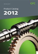
high torque precision Product Catalog
Open the catalog to page 1
For detailed technical information have a look at our website: www.gfc-antriebe.de
Open the catalog to page 2
This catalog is a description of our products. The data included in this catalog does not contain any indication regarding characteristics or suitability for certain or assumed application purposes. The technical data is subject to change without notice. Liability for illustrations and information included in the catalog shall be excluded for both GFC AntriebsSysteme GmbH and third parties acting on our behalf. (State November 2011)
Open the catalog to page 3
□ 1. Worm wheel sets Dimension sheets 40 - 80 16 E 2. Worm gear units Dimension sheets S 40.1 - 315.1 22 B9 3. Helical-worm gear units Dimension sheets SS 50.1 - 80.1 and SS 100 - 250 54 B 4. Worm-helical gear units Dimension sheets SST 97 -150 88 E 5. Double-worm gear units Dimension sheets DS 80.1 - 315.1 106 E 6. Elevator gear boxes Dimension sheets SSMVD 80 -160 110 Dimension sheets SSTKVD 97 - 150 112 Dimension sheets SSMVD 250 114 Information needed for processing orders 117 E 7. Escalator gear boxes Dimension sheets SOG 125 - 180 122 E 8. Slewing gear units Dimension sheets DRW 180 -285...
Open the catalog to page 5
>> GFC ANTRIEBSS YS T EME For more than 100 years, the name GFC stands for high precision, engineering ingenuity and customised solutions in producing worm gear units and drive systems. Lean hierarchies and short decision-making allow a exible and quick reaction to customer requirements. We offer long-lasting solutions and reliable system components in top material quality for machines and systems in virtually any size. Gears from our modular construction system can be modied and completed with the option of silenced brake motors, adjustable mechanisms, electronic speed controls or individual...
Open the catalog to page 6
our development department and also due to our staff‘s ongoing training programmes. It goes without saying that certications in compliance with EN ISO 9001 and EN ISO 14001, DNV and ABS have been signicant quality parameters and form a standard for the GFC production. Our highly qualied eld service and technical trained personnel as well as their in-depth consulting knowledge allow GFC to provide creative solutions to any drive technology task. We are ready for a challenge! >> Our product range includes: Worm gear units/motors – Centre distance a = 40 – 500 Helical worm gear units/motors – Centre...
Open the catalog to page 7
Specications for enquiries >> If the gearbox is to be exactly sized by GFC, we then request from you the following specications: 17. Transmission of power from the actuator machine to the gearbox 18. a) Temporarily high torque levels b) Additional forces to be absorbed by the bearing of the transmission (in N) and their direction, resulting from any additional loads on the shaft ends by gears for belts, V-belts, chain gearboxes of gears of any type 19. Device description (series, operation position) of the transmission (see Device Description Overview) 20. Are any particular properties required?...
Open the catalog to page 8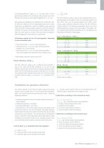
the operating efciency rating ≤ 0.5. This takes effect in worm gearboxes (according to the prevailing surface quality and toothbearing size at centre-increase angles ranging from = 2.5° to 4°. Self-locking worm gearboxes are inefcient due to their poor overall efciency rating and the correspondingly high loss of output (particularly considering the extensive installation space and long power-on times). In those actuator situations in which the self-locking effect is required, one should always verify whether the installation of a return block or a brake is the more practical solution. A self-locking...
Open the catalog to page 9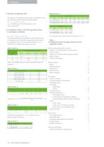
□ Selection of gearbox sizes The selection of the gearbox size is based on the greater of the two calculated values. Here, the following applies: T2N = nominal torque of the transmission on the slow-running shaft. □ For gearbox motors, the total operation factor The total operation factor calculated for each individual case of operation may not exceed the permissible output factor fv. For all gearbox motors, the permissible output factor fv is indicated in the output speed output overviews. At ambient temperatures of < -150 C, please consult us before taking further action. Agitators for materials...
Open the catalog to page 10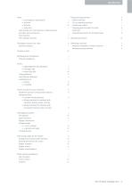
BTape-winding machines Textile machines Tin-can washing machines Transformer control » Turbo fans Traveling-grate actuators for ovens Turbo fans Typesetting machines for printing houses Feed actuators for tool machines, medical devices and other technical devices Feed channels Fish-washing machines HVibrating machines 0 Gangway actuators for ships Gearwheel pumps ^Washing machines Weapons installations, shooter actuators Wood-processing machines Infrared installations » Lightweight lifts (dumbwaiters) Loading fixtures M Main actuators for tool machines I Membrane pumps for the porcelain industry...
Open the catalog to page 11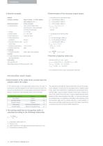
Actual: Actuator machine Working machine >> Characteristics Electric motor – S1 with relative stall torque MK/M = 2 Screw conveyor even, nearly impact-free, small masses to be accelerated of means of operation Ta = 126 Nm na = 100 1/min 1 start per hour >> Torque >> Output speed >> Start frequency >> Daily duration of operation 8 hours >> Running time per hour 25 min under load >> Ambient temperature -10°C to 30°C >> Rotation direction right Couplings >> Actuator machine elastic gear-ring coupling Gearbox >> Gearbox/gearbox (attachable design) working machine Lubrication with synthetic oil Operating...
Open the catalog to page 12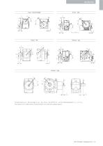
For gear types S 40 – 80 one stage, S 100 – 160, SS 50 – 80 and SST 97 – 150 the following applies: F‘R2 = 0,7 x FR2 The values for the radial loads are documented in the referring catalog chapters.
Open the catalog to page 13
>> MODUL AR UNIT S AND SPECIAL SOLU TIONS GFC worm gear sets consist of case-hardened and ground worm shafts combined with worm wheels made of high-quality, wear-resistant centrifugally cast or continuous cast bronze. Worm gear sets are characterised by shock-resistant, vibration-absorbing and low-noise gear teeth and provide large transmission ratios within a single stage. Self-locking at standstill is possible. We produce worm gear sets in standardised type ranges or according to the specications of our customers. Sophisticated and individual solutions are provided by using modern and high-precision...
Open the catalog to page 14All GFC AntriebsSysteme GmbH catalogs and technical brochures
 Heavy industry
11 Pages

- Precision gearhead
- Right angle gearhead
- Compact gearhead
- Solid-shaft gearhead
- Hollow-shaft gearhead
- Gear train gear reducer
- Transmission gearhead
- Single-stage gearhead
- Shaft gearhead
- Helical gear gearhead
- Low-noise gearhead
- Clamp gearbox
- High-precision gearhead
- High-speed gearhead
- Spur gearhead
- Large gear reducer
- Wheel gear reducer
- Double gearbox
- Shaft gear
- Elevator gear reducer