


P377.U001b

P377.U001b
An insufficiently deburred or overly rough cavity surface can damage the o-ring, leading to leaks. Refer to the catalog drawing for proper footprint.
Valve Assembly
Ensure cleanliness and proper state of the o-ring to reduce leakage risks. For cartridge valves, apply pressure and oscillating rotation to ease o-ring insertion. Subbase valves require alignment of fluid passage orifices. Body M5 valves must be screwed until mechanical stop.
Assembly Aides (Lubricant)
Use compatible lubricants sparingly to avoid internal pollution. If oil or grease is prohibited, use compatible volatile liquids like Ethanol or Isopropanol.
Assembly Tools
No specific tools are needed for cartridge valves, but avoid using force. Subbase valves require a screwdriver or Allen key, and Body M5 valves need a 15 mm spanner.
Tightening of Screws – Recommended Torque
Different screw types have specific torque requirements, generally around 0.45Nm for most screws.
Fluid Filtering
Valves are sensitive to pollution; filters are recommended based on orifice size. Ensure filter material compatibility with fluids.
Driving / Electrical Control of the Valve
Current driving is preferred due to stable electromagnetic force. Voltage driving requires sizing the circuit for up to 1.5x nominal voltage. PWM should have a frequency of at least 3kHz.
Duty Cycle
The duty cycle defines the maximum time a valve can be powered without deterioration. A 100% ED valve can be continuously powered.
Identification
Includes part number, nominal current, resistance, maximum pressure, serial number, and QR code.
Standard Troubleshooting
For no flow, check power supply, connector, and wire. For low flow, check for obstructions and power supply. For leakage, check assembly, screw torque, and o-ring cleanliness.
Catalog excerpts

fluid and motion control 3. Assembly aides (lubricant) 2 5. Tightening of the screws - recommended torque 3 7. Driving / Electrical control of the valve 4 10. Standard Trouble shooting 5 BEYOND STANDARD
Open the catalog to page 1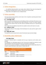
P377.U001a General user manual for P377 & P447 - An insufficient deburring and/or a too rough surface (>Ra0.8) of the cavity may damage the o'ring during the assembly process and thus, create internal or external leaks. - Please refer to the footprint on your catalog drawing The visual control of the cleanliness and the state of the o'ring before assembly greatly reduces the risk of external leakage. Exert a movement of combined pressure and oscillating rotation on the body of the valve, to ease the introduction of the o'ring whilst under radial compression. The aim is to create a dynamic movement...
Open the catalog to page 2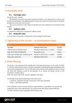
P377.U001a General user manual for P377 & P447 No specific tool is needed. - The M3x6mm screws are only used to maintain the valve is in its cavity and in no case to ease or help in its introduction. The tightening of the screws must only be carried out after the complete introduction of the valve into its cavity. - The use of a hammer or other object to introduce the valve axially by force should be strictly avoided. A screwdriver or Allen key is required for subbase screws. A 15 mm open-end spanner is required for final screwing of the M5 body. 6. Fluid filtering The stroke or the movement...
Open the catalog to page 3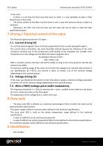
P377.U001a General user manual for P377 & P447 - If there is a risk that the fluid may flow back on itself, it is also advisable to place a filter downstream of the valve. - The active surface of the filter must be fixed in such a way that pressure decay is kept to a minimum. - Otherwise, the filter will limit the flow and the valve will not be able to meet the flow specifications given. The electrical signal may be one of 3 types : In a coil the electromagnetic force is directly proportional to the current passing through it. The current drive is therefore, the most favorable method because...
Open the catalog to page 4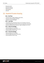
P377.U001a General user manual for P377 & P447 - Nominal current - Nominal resistance - Maximum pressure - Serial Number 10. Standard Trouble shooting - Check the power supply (voltage/current limit). - Check the connector (good insertion). - Check the wire (not damaged). - Inlet partially obstructed Check if there are no particles in the inlet. - Outlet partially obstructed Check if there are no particles in the outlet. - Courant insufficient Check the power supply (voltage/current limit). - Check assembly to the manifold. - Check the tightening torque of the screw. - Check cleanliness of the...
Open the catalog to page 5All GEVASOL catalogs and technical brochures
 Gevasol Profile Brochure
2 Pages
 Medical Emergency Equipment
4 Pages

Archived catalogs


- Stainless valve
- Water valve
- Pneumatic valve
- GEVASOL solenoid valve
- Electrical power supply connector
- Flap valve
- Check valve
- Electric valve
- GEVASOL gas solenoid valve
- GEVASOL 2-way solenoid valve
- GEVASOL NC solenoid valve
- Pressure limiter
- Gas valve
- GEVASOL direct-operated solenoid valve
- Industrial connector
- GEVASOL metal solenoid valve
- Single-stage pressure regulator
- Valve for industrial applications