- Catalogs
- GES Electronic & Service GmbH
- Series MCS - multipin HV connectors up to 5 kVDC
- Products
- Catalogs
- News & Trends
- Exhibitions
Series MCS - multipin HV connectors up to 5 kVDC
1 /9Pages

Series MCS - multipin HV connectors up to 5 kVDC
1 /9Pages
Catalog excerpts
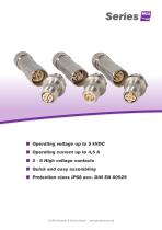
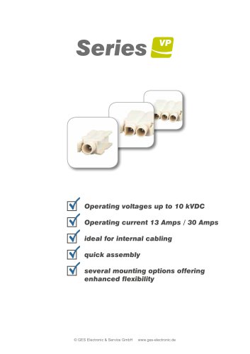
■ Operating voltage up to 5 kVDC ■ 2-6 High voltage contacts ■ Quick and easy assembling © GES Electronic & Service GmbH www.ges-electronic.de
Open the catalog to page 1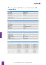
General characteristics and technical data Series MCS Housing Locking system threaded coupling Panel mount type round flange Housing material brass (CuZn) Surface plating Protection class acc. DIN EN 60529 (mated connector) Operating temperature Contacts 0.7 mm Termination method solder / crimp Rated current Volume resistance Contact diameter Wire size Contact material brass (CuZn) Contact plating Mating cycles Insulation material Flammability class Operating temperature Insulation material group Max. diameter of dielectric cable insulation Configurations Type © GES Electronic & Service GmbH
Open the catalog to page 2
Type MCS205 2-pole Electrical Values Insulation material Rated Current Type / Version / Description Mechanical drawing GB-MCS205 Receptacle, panel mount incl. female contacts 0.7mm GS-MCS205 plug, panel mount incl. male contacts 0.7mm plug, cable mount incl. male contacts 0.7mm KB-MCS205 Receptacle, cable mount incl. female contacts 0.7mm Cable mount Panel mount Clamping range (in mm) Screwed cable gland © GES Electronic & Service GmbH
Open the catalog to page 3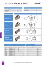
Electrical Values Insulation material Rated Current Type / Version / Description Mechanical drawing GB-MCS405 Receptacle, panel mount incl. female contacts 0.7mm GS-MCS405 plug, panel mount incl. male contacts 0.7mm plug, cable mount incl. male contacts 0.7mm KB-MCS405 Receptacle, cable mount incl. female contacts 0.7mm Cable mount Panel mount Clamping range (in mm) Screwed cable gland © GES Electronic & Service GmbH
Open the catalog to page 4
Type MCS605 Electrical Values Insulation material Rated Current Type / Version / Description Mechanical drawing GB-MCS605 Receptacle, panel mount incl. female contacts 0.7mm GS-MCS605 plug, panel mount incl. male contacts 0.7mm plug, cable mount incl. male contacts 0.7mm KB-MCS605 Receptacle, cable mount incl. female contacts 0.7mm Cable mount Panel mount Clamping range (in mm) Screwed cable gland © GES Electronic & Service GmbH
Open the catalog to page 5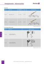
Components / Accessories Contacts Cross section In mm² (D) Mechanical drawing Coverings with thread Description Covering (inside thread) for types GS / GB 205 - 605 Mechanical drawing Covering (outside thread) for types KS / KB 205 - 605 © GES Electronic & Service GmbH
Open the catalog to page 6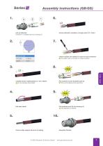
Assembly instructions (GB/GS) 1. part as delivered contacts (1), insulation part (2), housing (3) remove dielectric insulation of single wires (L3 = 5mm) crimp or solder one contact (1) each on every conductor ! Tin-solder must not remain on contact surface! carefully remove cable jacket (L2 = min. 30mm) ! Do not damage metal shield. Put contacts (1) into insulation part (2) ... Put in all contacts at the same time fold back shield Put insulation part (2) into housing (3) ! Pay attention to notches. remove cable support structure if existing © GES Electronic & Service GmbH Assembly finished
Open the catalog to page 7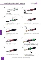
Assembly instructions (KB/KS) 1. Part as delivered cap (1), clamping rubber (2), outer cone (3), inner cone (4), contacts (5), insulation part (6), housing (7) Place inner cone (4) on cable Place cap (1), clamping rubber (2) and outer cone (3) on cable ! Respect correct order of parts (see picture). Remove dielectric insulation of single wires (L2 = 5mm) ! Do not damage conductor. Carefully remove cable jacket (L1 = 28mm) ! Do not damage metal shield. Do not damage dielectric insulation. Crimp or solder one contact (5) each on every conductor ! Tin-solder must not remain on contact surface! Fold...
Open the catalog to page 8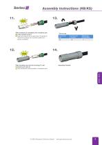
Assembly instructions (KB/KS) 11. Slide contacts (5) completely into insulation part (6) until contacts snap in ... Insert all contacts at the same time. Pull gently to check that contacts are correctly located and remain in position. wrench size housing Assembly finished Slide insulation part (6) into housing (7) until insulation part snap in ! Use notches for correct position of insulation part. © GES Electronic & Service GmbH
Open the catalog to page 9All GES Electronic & Service GmbH catalogs and technical brochures


- AMOT data connector
- AMOT round connector
- AMOT circular connector
- AMOT rectangular connector
- AMOT RF connector
- AMOT DIN connector
- AMOT crimp connector
- Voltage connector
- AMOT modular connector
- Feedthrough
- High-voltage connector
- AMOT USB connector
- Flange connector
- Cable feedthrough
- Multiple-element feedthrough
- Insulated feedthrough
- Vacuum feedthrough
- High-voltage feedthrough
- Electrically isolating connector