- Catalogs
- Gensco Equipment
- The BLUE SHARK Hammer Mill Shredder
The BLUE SHARK Hammer Mill Shredder
1 /10Pages

The BLUE SHARK Hammer Mill Shredder
1 /10Pages
Catalog excerpts
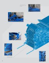
LARGE HOPPER TO LOAD MATERIAL REMOVABLE CRADLE
Open the catalog to page 2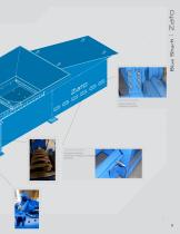
GUIDE WHEEL FOR HYDRAULIC PUSHER PROXIMITY SENSOR: TO DETECT HYDRAULIC PUSHER POSITION
Open the catalog to page 3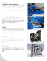
OPENING THE CAP OF THE UPPER GRIDS The two upper sections are closed and locked by means of hydraulic pins, driven by proportional solenoid valves controlled via a push-button panel and supplied by the control unit. Hydraulic cylinders open and lock these pins. When they are operated, the cylinders push the cap upwards so that you can safely and easily work on the grids. REF. 1 REMOVING THE CRADLE OF THE LOWER GRID The cradle, which houses the lower grid, is also closed by hydraulic pins. When the pins are removed, the two hydraulic cylinders push the cradle on two guides external to the mill...
Open the catalog to page 4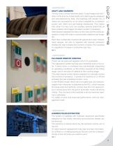
SHAFT AND HAMMERS The four rows of three hammers (total 12) are hinged onto the 7 discs of the rotor by 4 steel shafts and steel supports designed and manufactured by Zato. The bearings with double row of rollers are lubricated by an oil circuit supplied by a hydraulic control unit, filters and pre-heating resistances. This means that, when it is very cold, two auxiliary sensors check that oil flows properly and triggers the alarm system if necessary. Steel spacers separate the discs on the rotor and the entire assembly is fixed with bolts to ensure better elasticity and longer life. Each disc...
Open the catalog to page 5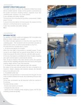
SUPPORT STRUCTURE (optional) The solid structure on which the machine is fitted has sturdy electro-welded beams. Inside, all the auxiliary components of the system are found: vibrating surface, magnetic drum, first unloading belt, hydraulic unit, power station. It has catwalks and safety railings. The structure (not including the auxiliary components) weighs about 15 tons. A second structure (about 9 tons) houses the engine and the reduction unit/hydrodynamic coupling unit. It also has catwalks and safety railings. MOVABLE ROTOR As standard, HP3000 models are equipped with a movable rotor (fitted...
Open the catalog to page 6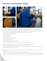
Reduction unit and hydraulic coupling Inside the steel electro-welded box you will find a pair of gears, the body of the hydrodynamic coupling, hub, input shaft, output shaft and hub, oil tank, fuel pump, the coupling, lubrication pump, bearings, two speed detectors (input and output), oil level detector and filters, oil pressure sensor and alarms, and air heat exchanger. Drainable hydraulic couplings facilitate disconnecting the engine from the loading. This results in remarkable advantages: - No-load engine start-up - Gentle loading start-up - Overload absorption - Impact on reduction unit...
Open the catalog to page 8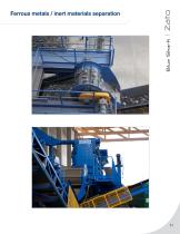
Ferrous metals / inert materials separation
Open the catalog to page 9All Gensco Equipment catalogs and technical brochures
 DTX SERIES
2 Pages
 The BLUE DEVIL
16 Pages
 CAYMAN
2 Pages
 DTX
DTX2 Pages
 F-Series
1 Page
 PMG-N Cable Shredder
4 Pages
 GSX Single Shaft
3 Pages
 Super Stripper 170
1 Page
 CSX2010
1 Page
 CSX
CSX1 Page
 Dynaset HMG
2 Pages
 CANMAG MAGNETS
2 Pages
 TYB and RC series brochure
2 Pages


Archived catalogs
 HYDRAULIC ALLIGATOR SHEARS
2 Pages
 vertical balers
1 Page
 H-MAG HYDRAULIC MAGNET
1 Page
 PM series
1 Page
- Power generator
- Industrial genset
- GENSO bending machine
- Tube bending cell
- Baler
- 60 Hz generator set
- Electric bending cell
- Hydraulic bending machine
- Single-phase generator set
- Primary shredder machine
- Single shaft shredder machine
- Vertical pulverizer
- Construction site generator set
- Wood shredder
- Automatic bending cell
- Lifting magnet
- Sheet metal shear
- Horizontal baling press
- GENSO stripping machine