
Catalog excerpts

Test & Embedded Electronics Make it real Test board for automotive products 24 channel switch matrix for EOL and impedance measurements.
Open the catalog to page 1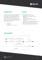
Lyn53 is an electronic board used in high speed EOL testers when the impedance between pins of the DUT must be measured. It is base on ultrafast solid state relays (SSR). This way, minimum swtiching time and unlimited operations can be assured. Due to its internal design, each DUT pin can be addressed to any of the following contacts: Backplane + Backplane Bypass to a mirror connector. Board size: 295 x 100 mm. Rackable board for 19” subracks. Expandable when combined with Lynx backplanes. CAN and USB controlled. Compatible with Lynx Test Scheduler software. 72 solid state relays for...
Open the catalog to page 2
Lynx53 is the first interface between the DUT and the FID and allows an easy implementation of any of the following features: • EOL fuctional testing for electronic modules. • ICT testing with external DMM. • Impedance testing beween DUT adjacent pins. • Short circuit detection. • Cables validaton. • Signal injection integrity supervision. DUT: Device Under Test. SSR: Solid Stat Relay. FID: Function Injection Device (device used to activate any DUT IO pin a certain signal with the objective to validate the associated funcion, e.g. ditigal input, analog input or power output). BKP:...
Open the catalog to page 3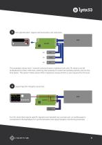
Current Supply HW optimitzation. Signal communication cost reduction. This examples shows how 1 channel communication modules (CAN, LIN, FR, others) can be multiplexed to other CAN lines, reducing the necessity for external modules and the cost for the final tester. This option makes sense when impedance measurement is also required for the test. FID: Signal injection integrity assurance. For EOL tests that require specific signals to be injected into a certain pin, an oscilloscope is connected to the backplane for synchronitzation and signal integrity monitoring purposes.
Open the catalog to page 4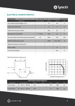
ELECTRICAL CHARACTERISTICS ABSOLUTE MAXIMUM RATINGS (Tamb = 25 °C, unless otherwise specified) PARAMETER TEST CONDITION DC or peak AC load voltage J2, J4 Load current (DC only) Output Ron max per channel Peak load current (AC/DC) Per each output, the following derating applies* Ambient temperature range Absolute maximum rating curve* Power supply Current consumption *Absolute maximum rating curve. * Absolute maximum rating curve. Load Current/A Ambient Temperature/ºC SWITCHING CHARACTERISTICS PARAMETER TEST CONDITION Turn-on time Turn-off time
Open the catalog to page 5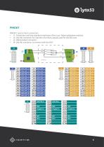
PINOUT PINOUT: Lynx53 has 4 connectors. J4 J4.13 GPIO_DUT_13 J4.1 • J1: Connection with the standard interfaces of the Lynx Tester backplane modules. J4.14 GPIO_DUT_14 J4.2 • J2: Use this connector for injection of primary signals used for the EOL test. J4.15 GPIO_DUT_15 J4.3 • J3. USB standard connector. J4.16 GPIO_DUT_16 J4.4 • J4: Use this connector to connect with the DUT. 13
Open the catalog to page 6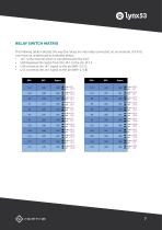
RELAY SWITCH MATRIX The follwing table indicates the way the relays are internally connected. As an example, the first row must be understood as indicated below: • J4:1 is the channel which is connected with the DUT. • U60 bypasses the signal from the J4:1 to the pin J2:14. • U36 connects the J4:1 signal to the pin BKP- (J1:7). • U12 connects the J4:1 signal to the pin BKP+ (J1:8).
Open the catalog to page 7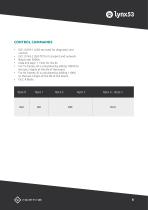
CONTROL COMMANDS • • • • • • • ISO 14229-1 (UDS services) for diagnostic and control. ISO 15765-2 (ISO-TP) for transport and network. Baud rate: 500Kb. Data link layer: 11 bits for the ID. For Tx frames, ID is calculated by adding 1000d to the last 2 digits of the SN of the board. For Rx frames, ID is calculated by adding 1100d to the last 2 digits of the SN of the board. DLC: 8 Bytes.
Open the catalog to page 8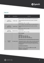
Enable relay The NumberRelay Parameter goes from 0x01 until 0x48 (0d72). Returns [ 110 , 247 , 1 , ] => OK 0x 2E F7 00 2A => 0x2A means 0d42, The relay Number 42. Disable relay The NumberRelay Parameter goes from 0x01 until 0x48 (0d72). Returns [ 110 , 247 , 0 , ] => OK
Open the catalog to page 9
(CAN_MANUFACTURER_SET_SERIAL) Sets a new Rx ID and Tx ID CAN in fuction of a serial number. When it sets a new serial number this is saved in NVM and new CAN RX id and TX id are calculated. New CAN RX ID will be: 1000 + (Serial_Number & 0xFF) New CAN TX ID will be: 1100 + (Serial_Number & 0xFF) For calculating the new CAN ID’s are considered only the 2 bytes of less weight of serial number. 0x 2E F7 01 1D => 0x1D means 0d29, The relay Number 29. The NumberRelay Parameter goes from 0x01 until 0x48 (0d72). Returns [ 110 , 247 , 1 , ] => OK 0x 2E F7 00 2A => 0x2A means 0d42, The relay Number...
Open the catalog to page 10
EXAMPLE - ID: Tx ID: 1055 (0x41F) / Rx ID: 1155 (0x483) - Goal is to close relay 25 - ID: 0x41F an Message: Data Bytes
Open the catalog to page 11
Test board for automotive products www.generationrfid.com Test & Embedded Electronics Make it real
Open the catalog to page 12All GENERATION RFID catalogs and technical brochures
-
 LYNX tester
11 Pages
-
 lynx50
13 Pages