
Catalog excerpts

Test & Embedded Electronics Make it real 0 Test board for automotive products 24 channel switch matrix for EOL and impedance measurements.
Open the catalog to page 1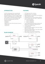
Lynx50 is a high speed CAN controlled solid state relay (SSR) multiplexer used to switch differential signals. It is suited to supply multiple boards in a sequential way, or to multiplex CAN control signals, so that test cost and complexity are reduced. Due to its internal design, each DUT pin can be addressed to any of the following contacts: · Backplane + · Backplane – · Bypass from PIN to PIN at the same connector. · Analog input. · Digital input. BLOCK DIAGRAM TEXT Board size: 295 x 100 mm. Rackable board for 19” subracks. Expandable when combined with Lynx backplanes. CAN and USB...
Open the catalog to page 2
Lynx50 is a good choice for the ICT testing of low input/output DUT circuits for any of the markets listed below: DUT: Device Under Test. SSR: Solid State Relay. FID: Function Injection Device (device used to activate any DUT IO pin a certain signal with the objective to validate the associated function, e.g. digital input, analog input or power output). BKP: Backplane. DDM: Digital multimeter. DI: Digital input. AI: Analog input. Automotive. Industrial. Telecommunications. Medical devices. PLC emulation. Automation. Control for visual inspection systems. Impedance and short circuit...
Open the catalog to page 3
Supply multiple boards in a sequential way. When a power supply is connected to the backplane we can supply multiple DUT’s in a sequential way. External devices activation. Any external device can be activated to execute a desired action. In the example a DC motor is activated for marking the DUT PCB.
Open the catalog to page 4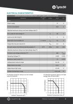
0 (**) Electrical characteristics for high voltaje relay (PVX6012PB ELECTRICAL CHARACTERISTICS ABSOLUTE MAXIMUM RATINGS (Tamb = 25 °C, unless otherwise specified) TEST CONDITION Power supply Current consumption Absolute maximum rating curve lowe voltage relay (*) VL Load current (DC Only) (*) Analog Inputs measure range Digital inputs low range Digital inputs high range Peak load current (AC/DC) (*) Output Ron max per channel (*) Per each output, the following derating applies (*) Absolute maximum rating curve high voltage relay (**) Transient overvoltage protection (**) Operating Voltage...
Open the catalog to page 5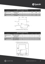
0 SWITCHING CHARACTERISTICS TEST CONDITION Maximum Turn-on time Maximum Turn-off time (*) Absolute maximum rating curve. SWITCHING CHARACTERISTICS PARAMETER TEST CONDITION Maximum Turn-on time Maximum Turn-off time (*) Absolute maximum rating curve.
Open the catalog to page 6
PINOUT PINOUT: Lynx53 has 4 connectors. • J1: Connection with the standard interfaces of the Lynx Tester backplane modules. • J2: Use this connector for injection of primary signals used for the EOL test. • J3. USB standard connector. • J4: Use this connector to connect with the DUT.
Open the catalog to page 7
RELAY SWITCH MATRIX The following table indicates the way the relays are internally connected. Some examples are described below to understand the table: • J4:1 is a channel which is connected with the DUT. • U2 connects the J4:1 signal to the pin BKP+ (J1:8). • U20 connects the J4:6 signal to the pin BKP- (J1:7). • U38 bypasses the signal from the pin J4:44 to the pin J4:11. • U48 bypasses the signal from the pin P1:1 to the pin P1:2. • AI1 is an analog input connected to the pin J4.34. • DI1 is a digital output connected to the pins J4.44 and J4.11. PRODUCT DATASH
Open the catalog to page 8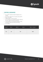
CONTROL COMMANDS • • • • • • • ISO 14229-1 (UDS services) for diagnostic and control. ISO 15765-2 (ISO-TP) for transport and network. Baud rate: 500Kb. Data link layer: 11 bits for the ID. For Tx frames, ID is calculated by adding 1000d to the last 2 digits of the SN of the board. For Rx frames, ID is calculated by adding 1100d to the last 2 digits of the SN of the board. DLC: 8 Bytes PRODUCT DATASH
Open the catalog to page 9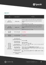
Enable relay The NumberRelay Parameter goes from 0x01 until 0x2B (0d43). Returns [ 110 , 247 , 1 , ] => OK 0x 2E F7 00 2A => 0x2A means 0d42, The relay Number 42. Disable relay The NumberRelay Parameter goes from 0x01 until 0x2B (0d43). Returns [ 110 , 247 , 0 , ] => OK Get Analog Input Voltage (Instantaneous) 0x 22 F7 05 05 Get Analog Input Voltage (Average) Where values mean: [ MSB, LSB ] for each Input: Input 1, Input 2, Input 3, Input 4, Input 5, Input 6, Input 7, Input 8, Input 9, Input 10 (48 , 242) would mean: (48 * 256^1) + (242 * 256^0) = 12.530 mV Get Analog Tick Count (Average)
Open the catalog to page 10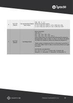
[ 98 , 247 , 4 , 3 ,] Get optoisolated Digital Where the number means: input values 0 = In1=> ON, In2=> ON // 1 = In1=> OFF, In2=> ON 2 = In1=> ON, In2=> OFF // 3 = In1=> OFF, In2=> OFF Return Example: [ 98, 247, 2, 255 , 255 , 255 , 255 , 255 , 255 , 255 , 251 , 255 , 255 , 252 , ] where Relay states are represented following the sequence: RelayState(0-3), RS(4-7), RS(8-11), RS(12-15), RS(16-19), RS(2023), RS(24-27), RS(28-31), RS(32-35), RS(36-39), RS(40-43*) Get Relays State *Relé number 43 (beginning from 0, otherwise it would be nº 44) is NOT USED. Then its state is returned as 00 but...
Open the catalog to page 11
EXAMPLE - ID: Tx ID: 1055 (0x41F) / Rx ID: 1155 (0x483) - Goal is to close relay 25 - ID: 0x41F an Message: Data Bytes
Open the catalog to page 12
Test board for automotive products www.generationrfid.com Test & Embedded Electronics Make it real
Open the catalog to page 13All GENERATION RFID catalogs and technical brochures
-
 LYNX tester
11 Pages
-
 lynx53
12 Pages