
- Catalogs
- GEMÜ Gebrüder Müller Apparatebau GmbH & Co. KG
- GEMÜ 675 Manually operated diaphragm valve


GEMÜ 675 Manually operated diaphragm valve
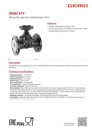
GEMÜ 675 Manually operated diaphragm valve
- Media Temperature: -10 to 100 °C
- Ambient Temperature: 0 to 100 °C
- Operating Pressure: 0 to 10 bar
- Nominal Sizes: DN 15 to 150
- Body Configurations: 2/2-way body
- Connection Types: Flange, Threaded connection
- Connection Standards: ANSI, BS, DIN, EN
- Body Materials: Options include cast iron and SG iron with various linings
- Diaphragm Materials: CR, EPDM, FKM, NBR, PTFE/EPDM, PTFE/FKM, PTFE/PVDF/EPDM
- Conformities: CRN, EAC, FDA, EU regulations, TA Luft
- Working Medium: Suitable for corrosive, inert, gaseous, and liquid media
- Temperature Ranges: Specified for different diaphragm materials
- Pressure: Operating pressure varies with diaphragm size and material
- Pressure Rating: PN 16
- Leakage Rate: A (according to EN 12266-1)
- Flange Connection (Code 51): Uses a flange according to BS 10 Table E standards, with face-to-face dimension following EN 558 series 7 and ISO 5752, basic series 7, applicable only for body configuration D.
- Threaded Socket DIN (Code 1): Follows the DIN ISO 228 standard for threaded sockets.
- Threaded Socket NPT (Code 31): Uses NPT female threads.
- Code 17: EN-GJS-400-18-LT (GGG 40.3), PFA lined.
- Code 81: EN-GJS-500-7 (GGG 50), PFA lined.
- Code 91: EN-GJS-500-7 (GGG 50), PP lined.
- Code 90: EN-GJS-400-18-LT (GGG 40.3).
- Dimensions are provided in millimeters and are specific to diaphragm sizes (MG) and nominal pipe sizes (DN/NPS).
- For flange connections, the number of bolt holes (n) and face-to-face dimensions (FTF) are specified.
- For threaded sockets, the number of flats (n) and other dimensions such as height (H), length (L), and thread size (R) are detailed.
Catalog excerpts
Features • Suitable for particulate and abrasive media • Various lining materials are available for a wide range of media • Standard integral optical position indicator The GEMU 675 2/2-way diaphragm valve has a metal handwheel and is manually operated. An integral optical position indicator is standard. • Body configurations: 2/2-way body • Connection types: Flange l Threaded connection • Connection standards: ANSI l BS l DIN l EN • Body materials: EN-GJL-250, cast iron material l EN-GJS-400-18-LT, SG iron material l EN-GJS-400-18-LT, SG iron material with butyl lining l EN-GJS-400-18-LT, SG iron material with hard rubber lining l EN-GJS-400-18-LT, SG iron material with soft rubber lining l EN-GJS-400-18-LT, SG iron material, PFA lined l EN-GJS-400-18-LT, SG iron material, PP lined l EN-GJS-500-7, ductile iron material, PFA lined l EN-GJS-500-7, ductile iron material, PP lined • Diaphragm materials: CR l EPDM l FKM l NBR l PTFE/EPDM l PTFE/FKM l PTFE/PVDF/EPDM • Conformities: CRN l EAC l FDA l Reg. (EU) No. 10/2011 l Regulation (EC) No. 1935/2004 l TA Luft (German Clean Air Act) Technical data depends on the respective configuration further information webcode: GW-675
Open the catalog to page 1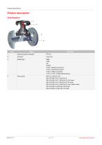
Product description
Open the catalog to page 2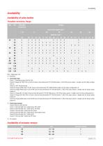
Threaded connection, flange
Open the catalog to page 3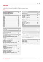
Order data The order data provide an overview of standard configurations. Please check the availability before ordering. Other configurations available on request.
Open the catalog to page 5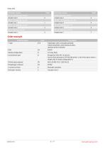
Order data
Open the catalog to page 6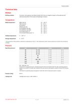
Technical data Working medium: Corrosive, inert, gaseous and liquid media which have no negative impact on the physical and chemical properties of the body and diaphragm material. Media temperature: NBR (code 2) PTFE/EPDM (code 54) PTFE/EPDM (code 5M) PTFE/FKM (code 5T) PTFE/PVDF/EPDM (code 71) All pressures are gauge pressures. Operating pressure values were determined with static operating pressure applied on one side of a closed valve. Sealing at the valve seat and atmospheric sealing is ensured for the given values. Information on operating pressures applied on both sides and for high purity...
Open the catalog to page 7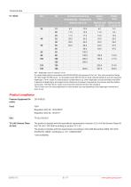
Technical data Product compliance Pressure Equipment Dir- 2014/68/EU ective: MG = diaphragm size, Kv values in m3/h Kv values determined in accordance with DIN EN 60534, inlet pressure 5 bar, Ap 1 bar, with connection flange EN 1092 length EN 558 series 1 (or threaded socket DIN ISO 228 for body material GGG40.3) and soft elastomer diaphragm. The Kv values for other product configurations (e.g. other diaphragm or body materials) may differ. In general, all diaphragms are subject to the influences of pressure, temperature, the process and their tightening torques. Therefore the Kv values may exceed...
Open the catalog to page 8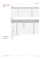
Technical data MG = diaphragm size, weight in kg Installation position: Flow direction: Optional
Open the catalog to page 9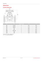
Dimensions in mm, MG = diaphragm size * CT = A + H1 (see body dimensions)
Open the catalog to page 10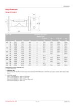
Dimensions in mm, MG = diaphragm size n = number of bolt holes Code 8: Flange EN 1092, PN 16, form B, face-to-face dimension FTF EN 558 series 1, ISO 5752, basic series 1, length only for body configuration D 2) Valve body material Code 17: EN-GJS-400-18-LT (GGG 40.3), PFA lined Code 18: EN-GJS-400-18-LT (gGG 40.3), PP lined Code 83: EN-GJS-400-18-LT (gGG 40.3), hard rubber lined Code 90: EN-GJS-400-18-LT (gGG 40.3)
Open the catalog to page 11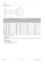
Dimensions in mm, MG = diaphragm size n = number of bolt holes Code 53: Flange EN 1092, PN 16, form A, face-to-face dimension FTF EN 558 series 7, ISO 5752, basic series 7, length only for body configuration D 2) Valve body material 3) Diameter deviates from standard
Open the catalog to page 12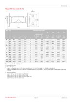
Dimensions in mm, MG = diaphragm size n = number of bolt holes Code 38: Flange ANSI Class 150 RF, face-to-face dimension FTF MSS SP-88, length only for body configuration D Code 39: Flange ANSI Class 125/150 RF, face-to-face dimension FTF EN 558 series 1, ISO 5752, basic series 1, length only for body configuration D Valve body material Code 17: EN-GJS-400-18-LT (GGG 40.3), PFA lined Code 18: EN-GJS-400-18-LT (gGG 40.3), PP lined Code 83: EN-GJS-400-18-LT (gGG 40.3), hard rubber lined Code 90: EN-GJS-400-18-LT (gGG 40.3)
Open the catalog to page 13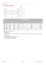
Dimensions in mm, MG = diaphragm size n = number of bolt holes Code 56: Flange ANSI Class 125/150 RF, face-to-face dimension FTF EN 558 series 7, ISO 5752, basic series 7, length only for body configuration D 2) Valve body material Code 17: EN-GJS-400-18-LT (GGG 40.3), PFA lined Code 81: EN-GJS-500-7 (GGG 50), PFA lined Code 91: EN-GJS-500-7 (gGG 5o), PP lined
Open the catalog to page 14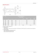
Dimensions in mm, MG = diaphragm size n = number of bolt holes Code 51: Flange BS 10 Table E, face-to-face dimension FTF EN 558 series 7, ISO 5752, basic series 7, length only for body configuration D 2) Valve body material Code 17: EN-GJS-400-18-LT (GGG 40.3), PFA lined Code 81: EN-GJS-500-7 (GGG 50), PFA lined Code 91: EN-GJS-500-7 (gGG 5o), PP lined
Open the catalog to page 15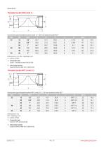
Connection type threaded socket (code 1) 1), SG iron material (code 90) 2) Dimensions in mm MG = diaphragm size n = number of flats Code 31: NPT female thread 2) Valve body material
Open the catalog to page 16
GEMÜ Gebr. Müller Apparatebau GmbH & Co. KG Fritz-Müller-Straße 6-8, 74653 Ingelfingen-Criesbach, Germany Phone +49 (0) 7940 1230 · [email protected] www.gemu-group.c
Open the catalog to page 17All GEMÜ Gebrüder Müller Apparatebau GmbH & Co. KG catalogs and technical brochures
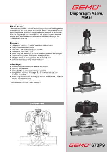 Diaphragm Valve, Metal
14 Pages
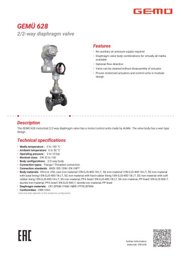 GEMÜ 628 2/2-way diaphragm valve
20 Pages
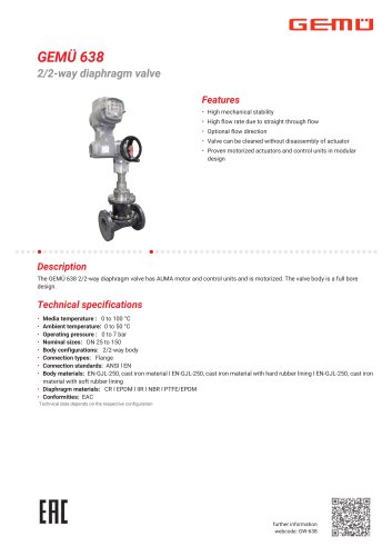 GEMÜ 638 2/2-way diaphragm valve
14 Pages
- Piping
- GEMÜ manual valve
- Fitting
- GEMÜ stainless steel valve
- GEMÜ control valve
- Hydraulic fitting
- GEMÜ water valve
- Ball valve
- Screw-in fitting
- GEMÜ pneumatic valve
- Pneumatic fitting
- GEMÜ threaded valve
- Electrically operated valve
- GEMÜ regulating valve
- GEMÜ flange valve
- GEMÜ shut-off valve
- Plastic hose
- GEMÜ electric valve
- Lever valve