- Catalogs
- GEMÜ Gebrüder Müller Apparatebau GmbH & Co. KG
- GEMÜ 611/671 Manually operated diaphragm valve


GEMÜ 611/671 Manually operated diaphragm valve
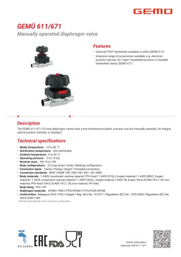
GEMÜ 611/671 Manually operated diaphragm valve
- Media Temperature: -10 to 80 °C
- Ambient Temperature: 0 to 60 °C
- Operating Pressure: 0 to 10 bar
- Nominal Sizes: DN 10 to 100
- Body Configurations: 2/2-way
- Connection Types: Clamp, Flange, Spigot, Threaded
- Connection Standards: ANSI, ASME, BS, DIN, EN, ISO, JIS, SMS
- Body Materials: Various including 1.4408, 1.4435, 1.4539, CW617N, EN-GJS-400-18-LT
- Diaphragm Materials: EPDM, FKM, PTFE/EPDM, PTFE/PVDF/EPDM
- Conformities: Belgaqua, EAC, FDA, Oxygen, EU and EC regulations, USP
- Connection Types: Includes threaded spigot (DIN 11851), cone spigot (DIN 11851), flange (EN 1092, JIS B2220, ANSI Class), and clamp (DIN/ASME, DIN/ISO).
- Valve Body Materials: Materials specified include 1.4435 (F316L) forged body, 1.4435 (BN2) forged body with Δ Fe < 0.5%, EN-GJS-400-18-LT (GGG 40.3) with PFA or PP lining, and 1.4408 with PFA lining.
- Diaphragm Size (MG): Indicated for each valve model.
- Nominal Pipe Size (NPS): Dimensions provided in millimeters for various NPS values.
- Face-to-Face Dimensions (FTF): Specified for different flange types and configurations.
- Tables provide detailed dimensions for each valve model, including diameter (øD), face-to-face length (FTF), height (H1), and bolt number (n).
- Each table is organized by connection type and material code, offering a comprehensive view of the available configurations.
- Exigencies: Emphasizes the importance of selecting the correct connection type and material for specific applications.
- Parameters: Detailed dimensions and material codes are crucial for ensuring compatibility and performance.
- Limitations: Certain dimensions are only applicable for specific body configurations.
Catalog excerpts
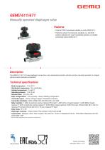
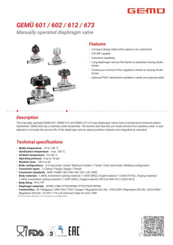
GEMU 611/671Manually operated diaphragm valve Features • Optional PVDF handwheel available in white (GEMU 611) • Extensive range of accessories available, e.g. electrical position indicator for "open" handwheel position or lockable handwheel clamp (GEMU 671) The GEMU 611/671 2/2-way diaphragm valves have a low-maintenance plastic actuator and are manually operated. An integral optical position indicator is standard. • Sterilization temperature: Not sterilizable • Body configurations: 2/2-way body l i-body l Welding configuration • Connection types: Clamp l Flange l Spigot l Threaded connection • Connection standards: ANSI l ASME l BS l DIN l EN l ISO l JIS l SMS • Body materials: 1.4408, investment casting material, PFA lined l 1.4435 (316L), forged material l 1.4435 (BN2), forged material l 1.4435, investment casting material l 1.4539 (904L), forged material l CW617N, brass l EN-GJS-400-18-LT, SG iron material, PFA lined l EN-GJS-400-18-LT, SG iron material, PP lined • Diaphragm materials: EPDM l FKM l PTFE/EPDM l PTFE/PVDF/EPDM • Conformities: Belgaqua l EAC l FDA l Oxygen l Reg. (EU) No. 10/2011 l Regulation (EC) No. 1935/2004 l Regulation (EC) No. 2023/2006 l USP Technical data depends on the respective configuration further information webcode: GW-611 / 671
Open the catalog to page 1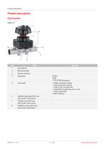
Product description
Open the catalog to page 2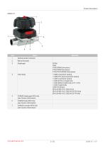
Product description
Open the catalog to page 3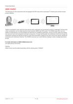
Product description GEMÜ CONEXO The interaction of valve components that are equipped with RFID chips and an associated IT infrastructure actively increase process reliability. Thanks to serialization, every valve and every relevant valve component such as the body, actuator or diaphragm, and even automation components, can be clearly traced and read using the CONEXO pen RFID reader. The CONEXO app, which can be installed on mobile devices, not only facilitates and improves the "installation qualification" process, but also makes the maintenance process much more transparent and easier to document....
Open the catalog to page 4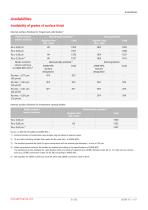
1) Surface finishes of customized valve bodies may be limited in special cases. 2) Or any other finishing method that meets the Ra value (acc. to ASME BPE). 3) The smallest possible Ra finish for pipe connections with an internal pipe diameter < 6 mm is 0.38 |jm. 4) When using these surfaces, the bodies are marked according to the specifications of ASME BPE. The surfaces are only available for valve bodies which are made of materials (e.g. GEMU material codes 40, 41, F4, 44)) and use connections (e.g. GEMU connection codes 59, 80, 88) according to ASME BPE. 5) Not possible for GEMU connection...
Open the catalog to page 5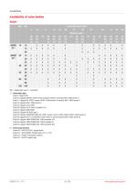
MG = diaphragm size, X = standard 1) Connection type Code 0: Spigot DIN Code 16: Spigot DIN EN 10357 series B (2014 edition; formerly DIN 11850 series 1) Code 17: Spigot EN 10357 series A/DIN 11866 series A formerly DIN 11850 series 2 Code 18: Spigot DIN 11850 series 3 Code 35: Spigot JIS-G 3447 Code 36: Spigot JIS-G 3459 schedule 10s Code 55: Spigot BS 4825, part 1 Code 59: Spigot ASME BPE/DIN EN 10357 series C (from 2022 edition)/DIN 11866 series C Code 60: Spigot ISO 1127/DIN EN 10357 series C (2014 edition)/DIN 11866 series B Code 63: Spigot ANSI/ASME B36.19M schedule 10s Code 64: Spigot...
Open the catalog to page 6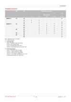
MG = diaphragm size, X = standard W = welded assembly Code 1: Threaded socket DIN ISO 228 Code 31: NPT female thread Code 6: Threaded spigot DIN 11851 Code 6K: Cone spigot and union nut DIN 11851 2) Valve body material Code 37: 1.4408, investment casting Code 40: 1.4435 (F316L), forged body Code 42: 1.4435 (bN2), forged body, A Fe < 0.5% Code 90: EN-GJS-400-18-LT (GGG 40.3)
Open the catalog to page 7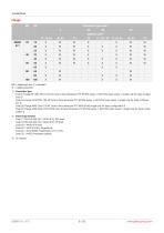
MG = diaphragm size, X = standard W = welded assembly Code 8: Flange EN 1092, PN 16, form B, face-to-face dimension FTF EN 558 series 1, ISO 5752, basic series 1, length only for body configuration D Code 34: Flange JIS B2220, 10K, RF, face-to-face dimension FTF EN 558 series 1, ISO 5752, basic series 1, length only for body configuration D Code 38: Flange ANSI Class 150 RF, face-to-face dimension FTF MSS SP-88, length only for body configuration D Code 39: Flange ANSI Class 125/150 RF, face-to-face dimension FTF EN 558 series 1, ISO 5752, basic series 1, length only for body configuration D...
Open the catalog to page 8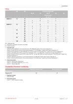
2) Valve body material Code 37: 1.4408, investment casting
Open the catalog to page 9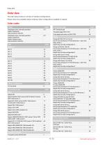
Order data The order data provide an overview of standard configurations. Please check the availability before ordering. Other configurations available on request.
Open the catalog to page 10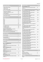
Order data
Open the catalog to page 11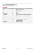
Order data
Open the catalog to page 12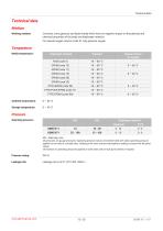
Technical data Working medium: Media temperature: Corrosive, inert, gaseous and liquid media which have no negative impact on the physical and chemical properties of the body and diaphragm material. For special oxygen version (code S): only gaseous oxygen Diaphragm material Ambient temperature: Storage temperature: Operating pressure: All pressures are gauge pressures. Operating pressure values were determined with static operating pressure applied on one side of a closed valve. Sealing at the valve seat and atmospheric sealing is ensured for the given values. Information on operating pressures...
Open the catalog to page 13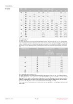
Technical data MG = diaphragm size Kv values in m3/h Kv values determined in accordance with DIN EN 60534 standard, inlet pressure 5 bar, Ap 1 bar, stainless steel valve body and soft elastomer diaphragm. The Kv values for other product configurations (e.g. other diaphragm or body materials) may differ. In general, all diaphragms are subject to the influences of pressure, temperature, the process and their tightening torques. Therefore the Kv values may exceed the tolerance limits of the standard. MG = diaphragm size, Kv values in m3/h Kv values determined in accordance with DIN EN 60534, inlet...
Open the catalog to page 14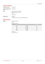
Technical data Technical data Product conformity Machinery Directive: Pressure Equipment Directive: Drinking water: Mechanical data * depending on version and/or operating parameters Weights in kg MG = diaphragm size
Open the catalog to page 15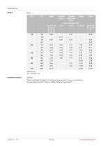
Technical data Weights in kg MG = diaphragm size Installation position: Observe the angle of rotation for optimized draining when it comes to installation. See separate document, "Angle of rotation technical information".
Open the catalog to page 16All GEMÜ Gebrüder Müller Apparatebau GmbH & Co. KG catalogs and technical brochures
 Diaphragm Valve, Metal
14 Pages
 GEMÜ 628 2/2-way diaphragm valve
20 Pages
 GEMÜ 638 2/2-way diaphragm valve
14 Pages