
- Catalogs
- GEA Wiegand
- VARINLINE®


VARINLINE®

VARINLINE®
GEA Tuchenhagen emphasizes the importance of sustainable and environmentally friendly production processes. Their products are designed to reduce energy, water, and chemical consumption, thereby minimizing environmental pollution. The company adheres to international standards, ensuring high hygiene and care standards for product processing.
Product Support and Services
GEA Tuchenhagen offers individualized engineering support, including digital tools like technical drawings and 3-D models. Their service concepts aim to minimize production downtime during maintenance.
Hygienic Valves and Components
These components are designed for easy maintenance and reliable function, contributing to consistent product quality. The VARIVENT® modular system enhances economic efficiency by optimizing stock keeping and reducing spare parts diversity. Special seal technology ensures long seal life and reduced maintenance frequency.
VARINLINE® Instrumentation
VARINLINE® instruments are designed for CIP/SIP processes, allowing cleaning and sterilization without dismantling. They are suitable for hygienic and aseptic processes, with self-draining housings that prevent dead zones.
VARITOP® and VARICOVER® Systems
The VARITOP® tank safety system is modular and customizable, offering applications from tank cleaning to pressure protection. The VARICOVER® product recovery system is designed for automatic operations, optimizing economic efficiency by recovering valuable products from pipelines.
Technical Data
GEA Tuchenhagen provides detailed specifications for their valves and components, including material properties, seal materials, and installation guidelines. The valves are suitable for outdoor use with specific protections and are designed to minimize stress during installation.
Certificates
The valves and components meet the requirements of EHEDG and 3-A SSI, ensuring efficient cleaning and safety. Optional certificates are available for specific applications.
- Materials: Components in contact with the product are made from 1.4404 (AISI 316 L), while non-contact parts use 1.4301 (AISI 304). Seals are available in EPDM, FKM, and HNBR, all FDA approved.
- Temperature and Pressure: Operating temperatures range from -30°C to 160°C, with pressure resistance up to 25 bar. The protection class is IP65 or IP66, depending on the component.
- Surface Quality: The internal surface roughness is Ra ≤ 0.8 μm for DN, OD, ISO, and Ra ≤ 1.2 μm for IPS.
- Order Codes: Each component has a specific order code based on its configuration, including process connection, nominal width, seal material, surface quality, illumination, certificates, and documentation language.
- Installation: Components can be installed with or without VARINLINE® housings or flanges, and various connection types are available.
- Components comply with EN 10204 for test reports and inspection certificates.
- ATEX certification is available for certain configurations.
- Choose appropriate seal materials and surface finishes based on the application environment.
- Consider the operational temperature and pressure requirements when selecting components.
- Pipe Dimensions: Detailed dimensions for nominal widths and process connections are provided, ensuring compatibility with existing systems.
- Pressure and Temperature Ranges: Specific ranges are outlined for each component type, ensuring they meet the necessary operational requirements.
The document provides detailed technical specifications and applications for VARINLINE® and VARIVENT® systems, focusing on process connections, flange connections, and expansion compensators. These systems are designed for hygienic and aseptic applications in various industries, including dairy, beverage, food, pharmaceutical, and biotechnology.
VARINLINE® Adapter and VARIVENT® Housing
The VARINLINE® adapter allows for the integration of in-line control and measurement within a VARIVENT® housing, ensuring a dead-zone-free environment. However, it is not suitable for certain sampling valve types (TSVN or TSVU).
VARIVENT® Flange Connections
These connections use an O-ring for sealing, protected by a metal stop to prevent displacement at high flow rates. The flange connections are available in complete sets or as individual components, including blind flanges for pipeline shutdowns.
Technical Specifications
Materials used include 1.4404 stainless steel with a surface roughness of Ra ≤ 0.8 μm. Seal materials are available in EPDM, FKM, and HNBR, all FDA approved. The document provides detailed dimensions and weights for various nominal widths and types of connections.
VARICOMP® Expansion Compensators
These compensators address thermal expansions and tensions in pipeline systems, suitable for aseptic processes. They feature a dead-zone-free design, are CIP/SIP-able, and have a maximum compensation distance of 8 mm. The compensators are equipped with vulcanized support rings for high-pressure loads.
VARIVENT® Valves
The document outlines various valve types, including control, sampling, overflow, constant pressure, vacuum, and safety relief valves. Each type is designed for specific functions such as maintaining constant pressure, providing excess pressure protection, and ensuring hygienic sampling.
Conclusion
The VARIVENT® system's modular design allows for customization to meet specific process requirements, enhancing economic efficiency and optimizing stock management. The document emphasizes the importance of maintaining low operation and maintenance costs while meeting high technological and quality standards.
The document provides a detailed technical overview of VARIVENT® control valves, focusing on their design, functionality, and applications. These valves are integral to process control technology, impacting the quality and efficiency of operations in industries such as food production, pharmaceuticals, and chemical processing.
Valve Function and Design
Control valves act as actuators in control loops, functioning as throttle devices to set desired flow rates by altering pressure loss in pipelines. The VARIVENT® valves feature a linear or equal percentage control cone and a valve seat within a cleanable, dead zone-free housing. The modular design allows for easy assembly and maintenance, with options for soft or metallic sealing.
Technical Specifications
The valves are available in two types: Type S with a diaphragm actuator and Type P with an air/spring actuator. Both types offer high precision and flexibility, with various Kvs values available for different nominal widths. The valves are designed to meet high hygiene standards, essential for applications in food and pharmaceutical industries.
Applications
VARIVENT® control valves are used for pressure regulation, flow control, and mixing of liquids. They are suitable for temperature control in heat exchangers, tank pressure control, wort aeration, and dosing of different media. The valves support efficient cleaning procedures like CIP and SIP, ensuring germ-free processes.
Special Features
The valves' modular design allows for flexible adaptation to various application conditions. They feature detachable clamp connections for low maintenance and assembly, and positioners for precise stroke determination. The valves are available with linear or equal percentage control cones, and the sealing technology ensures long service life and minimal downtime.
Control Characteristics
The control characteristic of a valve is determined by the Kv value's dependence on the stroke. Linear characteristics are used when the valve causes significant pressure loss, while equal percentage characteristics are recommended for most applications. The valves are designed to prevent water hammers and ensure reliable modulating functions.
Sealing and Material
The valves use a special seal technology with metallic stops for defined seal deformation, enhancing durability. They are available with FDA-compliant sealing materials like EPDM, FKM, HNBR, and FFKM. The material in contact with the product is AISI 316L, ensuring high hygiene standards.
Conclusion
VARIVENT® control valves offer a versatile and reliable solution for various industrial applications, with a focus on hygiene, efficiency, and adaptability. Their modular design and advanced sealing technology make them suitable for demanding environments, ensuring high performance and minimal maintenance.
The document outlines the specifications for VARIVENT® control valves, including surface quality, actuator types, and connection fittings. The surface in contact with the product has a roughness of Ra ≤ 0.8 μm for DN and OD, and Ra ≤ 1.2 μm for IPS. The external housing surface is matte blasted. The positioner is an I/P type 3725, and the actuator is a diaphragm type with air/spring mechanism. Connection fittings are welding ends, and the valve seat version is a clamped seat ring.
Technical Data:
The control valves have linear control characteristics and are recommended to flow against the closing direction. Materials in contact with the product are 1.4404 (AISI 316L), while non-contact materials are 1.4301 (AISI 304). Seal materials include EPDM, FKM, and HNBR. The ambient temperature range is 0 to 45 °C, with an air supply pressure of 4–7 bar (58–101.5 PSI). Product pressure varies by size, with DN 25–65 and OD 1"–2 ½" supporting 0–16 bar, and DN 80–100 and OD 3"–4" supporting 0–10 bar.
Valve Dimensions:
The document provides detailed dimensions for various nominal widths (DN and OD) and diaphragm surfaces (175 cm², 350 cm², 750 cm²). It includes measurements for diameter, height, and other critical dimensions.
Order Code Description:
The order code for VARIVENT® valves is structured based on valve type, housing combinations, nominal width, non-actuated position, control cone seal, Kvs value, actuator, actuation pressure, actuator material, seal material, surface quality, connection fittings, and options. Specific codes are provided for different configurations.
Positioner Function:
Positioners convert input signals into output signals to control valve positions. They compare set values from a controller to the valve stroke and adjust pneumatic actuator pressure accordingly. Positioners can handle both pneumatic and electro-pneumatic signals, with features like automatic setup and error recognition.
Positioner Types:
Different types of positioners are mentioned, including pneumatic (p/p) and electro-pneumatic (i/p) types. Electro-pneumatic positioners use analog or digital signals and convert them into required pressures. Special features of digital positioners include simple operation, automatic setup, and error recognition.
The document outlines the specifications for VARIVENT® control valves, focusing on materials, pressure ratings, and dimensions. The materials in contact with the product are made of 1.4404 (AISI 316L), while those not in contact are 1.4301 (AISI 304). Seal materials include EPDM, FKM, and HNBR. The ambient temperature range is 0 to 45 °C, with air supply pressure between 5–8 bar. Product pressure varies by size, with DN 25 – 65 and OD 1" – 2 ½" supporting 0–16 bar, and DN 80 – 100 and OD 3" – 4" supporting 0–10 bar. The surface in contact with the product has a roughness of Ra ≤ 0.8 μm, and the external housing surface is matte blasted.
The control system uses the T.VIS® P-15 positioner, which is a cost-effective solution with a precise path measuring system. It allows for manual and automatic operation, with feedback provided via LED indicators. The system supports a range of configurations and is protected to IP66 standards.
The document details the configuration options for VARIVENT® valves, including actuator types, seal materials, and connection fittings. The valves can be configured for different nominal widths and actuator types, with options for spring-to-close or spring-to-open positions. The document also provides a detailed order code structure for specifying valve configurations.
Dimensions and weights for various nominal widths are provided, detailing the pipe housing, actuator dimensions, and valve weights. This includes specific measurements for DN and OD sizes, ensuring compatibility with different system requirements.
The T.VIS® P-15 positioner features automatic initialization, simple operation, and manual process valve operation. It provides valve status display via LED and supports open/close position feedback. The positioner is designed for high-quality pneumatic fittings and offers significant cost reduction potential.
The VARIVENT® control valves are suitable for horizontal tank valves and other applications where complete drainage is required. The document highlights the versatility of the VARIVENT® system, allowing for various configurations and applications in different industrial settings.
This document provides technical specifications and options for VARIVENT® valves, focusing on control valves with special functions. It includes details on manual and pneumatic actuators, valve types, and additional features such as limit stops and sterile locks.
Specifications:- Material: 1.4301 stainless steel.
- Surface Finish: Turned, Ra ≤ 1.6 μm.
- Nominal Widths: Metric DN 25 – 150, Inch OD 1" – 6", Inch IPS 2" – 6".
- VARIVENT® Control Valve P: Suitable for manual operation with a handwheel or crank, depending on size.
- VARIVENT® Control Valve S: Equipped with diaphragm actuators and additional manual adjustments.
- Manual Actuator: Allows manual operation of pneumatic valves during power failures or maintenance.
- Limit Stop: Mechanically adjustable to limit valve stroke, not compatible with sterile locks.
- Sterile Lock: Prevents contamination by separating valve disc surface from the atmosphere.
- Double Stem Guidance: Reduces vibrations and is standard in certain valve types.
- Kv Value Calculation: Provides formulas for determining flow rates and pressure differentials.
- Actuator Selection: Based on diaphragm surface area and required closing force.
- Control Cone Selection: Depends on pressure reduction and flow characteristics, with options for linear or equal-percentage curves.
- Nominal Width and Actuator Size: Determined by flow volume and pressure requirements.
Includes sections for customer details, medium type, process conditions, and valve specifications to assist in selecting the appropriate VARIVENT® control valve.
- VARIVENT® Type I: Installed upright, can be actuated pneumatically or manually, and allows for smaller sample volumes.
- VARINLINE® Type TSVN and TSVU: Can be installed vertically or horizontally, compatible with VARINLINE® products, and available as aseptic valves with stainless steel bellows.
- VARIVENT® Type T/09: A fully automatic mixproof sampling and dosing valve, allowing for cleaning or sterilization immediately after sampling.
The document provides detailed technical specifications and configurations for VARIVENT® valves, including overflow, constant pressure, and safety relief valves. These valves are designed for use in industries such as food, beverage, and pharmaceuticals, meeting various international standards.
Specifications
- Material: The valves are made from high-quality materials such as 1.4404 (AISI 316L) for parts in contact with the product and 1.4301 (AISI 304) for other parts. Seal materials include EPDM, FKM, and HNBR.
- Surface Finish: Internal surfaces have a roughness of Ra ≤ 0.8 μm, and external surfaces are matte blasted.
- Temperature and Pressure: Ambient temperature ranges from 0 to 45 °C, with a maximum air supply pressure of 8 bar (116 psi) and product pressure up to 10 bar (145 psi).
Valve Types and Functions
- Overflow Valves: These include adjustable set pressure and pneumatic lifting features, with various actuator types and configurations available.
- Constant Pressure Valves: Designed to maintain constant pressure at the valve's input side, they feature a PTFE valve disc for low friction and resilience against corrosive fluids.
- Safety Relief Valves: Developed for hygienic applications, these valves protect systems from excess pressure and are available with manual or pneumatic lifting mechanisms.
Order Codes and Configurations
The document outlines the order code structure for different valve configurations, detailing positions for valve type, housing combinations, actuator type, seal material, and more. Specific configurations are available for different nominal widths and connection fittings.
Technical Data and Dimensions
Tables provide detailed dimensions and weights for various valve sizes, including nominal width, stroke, and weight. The document also includes Kvs values for flow rates and recommended flow directions.
Special Features
VARIVENT® valves offer features such as hygienic design, simple maintenance, and good control properties. Safety relief valves are designed for easy cleaning and are equipped with HyTight Assembly for optimal hygiene.
- Materials: Product-contact materials are made of 1.4404 (AISI 316L), while non-contact materials are 1.4310 (AISI 304). Seal materials include EPDM.
- Temperature and Pressure: Ambient temperature ranges from -10 to 130°C, with air supply pressure at 6 bar and set pressure between 0.5 to 10 bar.
- Surface Quality: The surface in contact with the product has a roughness of Ra ≤ 0.8 μm, with options for Ra ≤ 0.4 μm through electro-polishing.
- Safety Relief Valves: Available in types 483 and HyCom, with options for manual or pneumatic lifting, and various connection types including VARIVENT® grooved flange.
- Vacuum Valves: Designed to protect tanks against negative pressure, featuring quick reaction times and optional heating elements for freeze protection.
- Limit Stop: Allows adjustment of the valve to the required outlet mass flow to prevent unstable function behavior.
- Heating Facility: Provides freeze protection for the valve seat, ensuring functionality at temperatures below 0°C.
- Cleaning Module: Facilitates hygienic cleaning of the valve seat area, requiring a VARIVENT® grooved flange connection.
- VARITOP® System: A modular tank safety system used primarily in the brewing industry for pressure regulation and protection against over- or under-pressure.
- Vacuum Valves: Used in conjunction with the VARITOP® system, offering protection from dirt particles and ensuring quick response to vacuum conditions.
- Feedback mechanisms, proximity switches, and pneumatic lifting actuators are available for enhanced control and monitoring.
- Various seal materials and surface finishes can be selected based on specific application requirements.
The VARITOP® Tank Safety Systems are designed to ensure the safety and cleanliness of tanks used in various industrial processes. Key components include safety relief valves, vacuum valves, switch-over modules, and cleaning modules.
1. Safety Relief Valve
The safety relief valve, available in types 488 or HyCom, protects tanks from excess pressure. Detailed design information is available in section 4.5.
2. Vacuum Valve
VARIVENT® vacuum valves protect tanks from negative pressure below -2.5 mbarg, ensuring quick response times. More details are in section 4.6.
3. Switch-over Module
This module manages the transition between gassing, degassing, and cleaning processes. It automatically switches paths based on flow rates, with specific settings for rotating jet cleaners.
4. Central Connection
The central connection uses a VARIVENT® flange, ensuring a secure attachment to the tank.
5. Pressure Transmitter
An optional pressure transmitter monitors the pressure in the tank's headspace, using a VARINLINE® N 50/40 connection.
6. Cleaning Module
This module facilitates hygienic cleaning of the safety relief valve's entrance side, using a connection at the switch-over module.
7. Cleaning Process
The system supports various cleaning devices, including cleaning lances and rotating jet cleaners. The cleaning process is optimized for efficiency, with specific flow rates required for effective operation.
8. Technical Specifications
Materials in contact with the product are made of 1.4404 stainless steel, with EPDM seals. The system operates within specific temperature and pressure ranges, ensuring compatibility with industrial standards.
9. Options and Accessories
Additional options include sight glass with illumination, special flanges for larger cleaners, and GEA Tuchenhagen level probes for overfill protection.
Conclusion
The VARITOP® Tank Safety Systems provide comprehensive solutions for tank safety and cleanliness, with customizable options to meet specific industrial needs.
- Specifications: The systems are made from material 1.4404 with EPDM seals, suitable for ambient temperatures between 0 to 45°C and operating temperatures below 80°C. They operate with an air supply pressure of 6 to 8 bar and a product pressure of 10 bar.
- Dimensions: Detailed dimensions are provided for different nominal widths (DN 100, DN 125, DN 162) including various height and length measurements.
- Safety Relief Valves: Maximum values for safety relief valves are specified for types 488 and HyCom, with dimensions for different nominal widths.
- Connection and Cleaning: Systems use VARIVENT® flange connections and include options for cleaning devices like rotating jet cleaners and cleaning lances.
- Purpose: These systems optimize economic efficiency by recovering valuable products from pipelines, reducing waste and cleaning media consumption.
- Types: The systems are available in automatic, semi-automatic, and manual configurations, each with varying levels of automation for product recovery.
- Applications: Used in industries such as food, beverage, and personal care for products like yogurt, fruit juice, shampoo, and toothpaste.
- Features: The systems are designed for safe operation with closed pipe systems, automatic function modes, and components certified to 3A standards.
- Only piggable valves matching the geometry of the GEA Tuchenhagen double ball pig can be used.
- Consistent interior diameter throughout the pipe system is required.
- Avoid sharp-edged and strongly sagging welds.
- Connection fittings with rounded internal transfers are permissible.
- No seals should protrude into the pipe.
- Standard pipe bends with a small middle radius can be used, but the number of bends should be minimized.
- Use pipe bends with low ovality, with tolerances up to ± 1.5% of the outside diameter across the entire bend length.
- Pig speed control is crucial; it should not exceed 0.5 m/s at the pig station to prevent damage.
- Avoid running the pig in a dry pipeline or returning it after pushing out water when using compressible media like air.
- Stick-slip effect can occur if these conditions are not met, except with slippery products like shampoo and vegetable oils.
- Available for semi-automatic, automatic, and manual operations.
- Includes components like pig catching pipe/station, pig driving medium valves, pig stopper, and pig T-piece.
- Free of dead zones and fully CIP-/SIP-able, integrated into the product path.
- Pig retention cylinders and guidance keep the pig in position during flooding with product or cleaning media.
- Ensures best cleaning with complete residual emptying.
- Mechanically stops the pig; not flooded with cleaning media.
- Standard valve unit consists of two combined ECOVENT® valves (NL and WK).
- Prevents mixing between product and pig driving medium.
- Allows connection of pig driving medium valves and adaptation of pressure gauges or transmitters.
- Standard valve unit ensures complete cleaning and prevents mixing of media.
- Automatically operated, used for precise positioning of pigs.
- Prevents pig from leaving the launching station in case of vacuum.
- Used as product inlet and outlet in pigging lines.
- Prevents canting of the pig by having a smaller lateral socket width.
- Made from wear- and temperature-resistant materials, compatible with products.
- Double ball shape ensures optimal passage through bends and T-pieces.
- Contains stainless steel-encapsulated magnets for detection.
- Material in contact with product: 1.4404.
- Seal material: EPDM (FDA compliant).
- Ambient temperature: 0 to 45 °C.
- Max product pressure varies by size, up to 16 bar (232 psi).
- Surface in contact with product: Ra ≤ 0.8 μm.
- Material: Components in contact with the product are made from 1.4404 (AISI 316L) stainless steel, ensuring durability and compliance with hygiene standards.
- Seal Material: Options include EPDM, FKM, and HNBR, all FDA approved, suitable for various operational conditions.
- Surface Quality: Internal surfaces have a roughness of Ra ≤ 0.8 μm, with external surfaces either matte blasted or ground.
- Pressure Ratings: Product pressure varies by nominal width, with DN 25 to DN 65 and OD 1" to OD 2 ½" rated at 16 bar, and DN 80 to DN 100 and OD 3" to OD 4" rated at 10 bar.
- Pig Catching Pipe: Available in various nominal widths, with detailed dimensions provided for each size.
- Pig Driving Medium Valves: Feature pneumatic actuators and are designed for pressures up to 16 bar for smaller diameters and 10 bar for larger ones.
- Pig Stopper and T-Piece: Designed for efficient product recovery and cleaning, with options for proximity switches and various connection fittings.
- Product Push-Out: The pig is driven through the pipeline by a medium, pushing residual product towards the receiving station.
- Cleaning: The pig and pipeline are cleaned during the cleaning cycle, with specific procedures for different system configurations.
- Pig Return: After cleaning, the pig is returned to the launching station using a gaseous medium.
- EMI/1 and EMII/1 Systems: Automatically operated systems with specific cleaning and inspection protocols.
- DM/1 System: Offers flexibility with product push-out in two directions and operation with one pig, suitable for foaming products.
- VARICOVER® DM/1: This automatic system involves manual insertion of the pig, which is then pushed through the pipeline to recover residual product. Cleaning is manual.
- VARICOVER® SP1/SP2: Semi-automatic systems where the pig runs automatically, but cleaning is manual. SP2 includes a ball valve for increased safety.
- VARICOVER® MP1/MP2: Fully manual systems with optional semi-automatic operation. MP2 includes ball valves for better control and safety.
- Product Filling: To avoid foam formation when filling descending pipelines, a product recovery system is used to separate product and air.
- Operation: The pig is driven through the pipeline using a driving medium, typically water or air, to push out residual product.
- Cleaning: Pigs are manually cleaned outside the system after use.
- Pig Detector: Used to locate stationary pigs along the pipeline, suitable for explosive atmospheres.
- Pipe Brackets and Magnetic Sensors: Used to detect pigs in motion and control their speed.
- Test Materials: Used to assess the chemical resistance of pig materials.
- Ensure consistent pipe diameter and minimize sharp bends to facilitate pig movement.
- Use appropriate driving media based on product characteristics (e.g., slippery products may require air).
- Consider ball valves for enhanced safety and control during pig insertion and removal.
- Details on housing and nominal widths, including jacketed valve housings for temperature control.
- Specifications for increased pressure levels and material options for different applications.
The document outlines the specifications for VARIVENT® valves, including control, overflow, and sampling valves. The materials used are primarily 1.4404 (AISI 316L) for DN 25 – 80 and OD 1" – 3", and 1.4462 for DN 100 and OD 4". The pressure levels are specified as PS 20 bar for the valves and PS 16 bar for jacketed housings.
Nominal Widths and Valve Types:
Available nominal widths range from DN 10 to DN 150 in metric and OD 1" to 6" in inches. The document specifies various valve types, including VARIVENT® control valve S, P, overflow valve Q, and sampling valve I, N, U.
Mix-Matched Housing Combinations:
The document provides detailed tables for mix-matched housing combinations, indicating the compatibility of different upper and lower housing sizes. It emphasizes that not all valve types can be mix-matched and advises contacting GEA Tuchenhagen for feasibility.
Seal Materials:
The document discusses the use of FFKM (FDA) seal materials, known for high thermal and chemical resistance, combining properties of PTFE and Viton. Operating temperatures range from −10 °C to 230 °C.
Surface Quality Options:
Various surface quality options are available, with inner surface roughness ranging from Ra ≤ 0.4 μm to Ra ≤ 1.2 μm. Electro-polishing is mentioned as a method to improve surface quality, enhancing corrosion resistance.
Connection Fittings:
The document details various connection fittings, including VARIVENT® flange connections, pipe fittings according to DIN 11851, and hygienic flange connections according to DIN 11853-2. It specifies the use of O-rings for sealing and provides dimensions for different nominal widths.
Technical Data:
The document includes technical data for materials, standards, and seal materials, emphasizing compliance with FDA standards and DIN specifications.
Order Code Description:
The document provides a detailed breakdown of the order code for options, including nominal width, surface quality, and connection fittings, with examples for incorporation into orders.
The document outlines the specifications for valve components, emphasizing the importance of test reports and inspection certificates according to European standard EN 10204. It specifies that inspection certificates 3.1 can be issued for housings and product-wetted parts if requested at the time of order.
Identification Options
Various identification options for valves are described, including engraved metal plates, adhesive ID tags, and valve identification with TAG numbers. These options ensure clear identification and allocation of valves, with specific configurations available for different markets, such as the US version.
3-A Sanitary Standards
The document highlights the compliance of valves with 3-A Sanitary Standards, which are crucial for the food, beverage, and pharmaceutical industries. It details the requirements for valve design and identification, including surface quality specifications.
Lubricants and Spare Parts
Information on lubricants and spare parts for various valve types, including expansion compensators and vacuum valves, is provided. The document lists article numbers for different materials and sizes, ensuring easy ordering and maintenance.
Seal Sets
Detailed descriptions of seal sets for different valve types, such as VARIVENT® and VARINLINE®, are included. These sets consist of various seals that come in contact with the product, with specific configurations and article numbers provided for different materials.
Control and Feedback Systems
The T.VIS® control top system is described as a modular solution for controlling and monitoring valves. It features high protection classes, ease of cleaning, and maintenance-free electronic modules. Various models are available, including those for potentially explosive areas.
Certificates
The document concludes with information on certificates for control and feedback systems, highlighting compliance with EHEDG and 3-A Sanitary Standards for hygienic engineering and design.
- T.VIS® M-15: Features a modular system with manually adjustable sensors, a 24 V DC interface, and optional solenoid valves. It supports DeviceNet and AS-Interface communication standards and offers protection class IP66.
- T.VIS® A-15: Equipped with a high-precision path measuring system for automatic position recognition. It supports 24 V DC, AS-Interface, and DeviceNet interfaces, with protection class IP66.
- Both systems offer LED status indication, flexible modularity, and high-quality pneumatic fittings.
- The T.VIS® A-15 includes quick automatic initialization and tamper-proof settings, reducing energy consumption and operating costs.
- Operating voltage for both systems is 24 V DC, with specific current consumption and protection features.
- Ambient temperature range is −20 to 55 °C, with air supply pressure between 2 to 8 bar.
- Both systems comply with ISO 8573-1:2010 standards for solid, water, and oil content.
- Order codes for both systems are provided, detailing options for solenoid valves, feedback types, interface types, and additional features like protection classes and connection types.
Catalog excerpts

Hygienic Valves and Components Business Line Hygienic Valve Technology Catalog 2018
Open the catalog to page 1
Legal notice Publication date: July 2018 The publication of specifications, technical data and information in written or electronic form does not release the user from the responsibility of checking for themselves all products delivered by us for suitability for the application(s) intended. These may be subject to change without prior notification. Errors and printing errors excepted – we assume no liability for the correctness of specifications given. The general terms and conditions of delivery apply. All rights reserved – copyright on all contents. The ® symbol in this catalog identifies a...
Open the catalog to page 3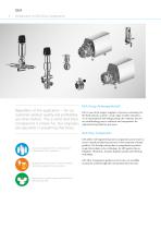
Introduction to GEA Flow Components Regardless of the application – for our customers product quality and profitability are what matters. This is what GEA Flow Components is known for. Our engineers are specialists in everything that flows. GEA is one of the largest suppliers of process technology for the food industry and for a wide range of other industries. As an international technology group, the company focuses on world-leading process solutions and components for sophisticated production processes. Around one quarter of the milk processed is handled by GEA equipment Roughly every second...
Open the catalog to page 8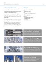
Introduction to GEA Flow Components State-of-the-art hygienic design GEA Flow Components meet the highest hygienic standards where required, such as EHEDG and 3-A standards. • Beverage – Beer, juice, smoothie products … • Dairy – Milk, yoghurt, cheese … • Food – Sauces & cremes, ketchup, mayonnaise … • Pharma/Biotech – harmaceuticals, biotechnology products, P cosmetics & health care … • Chemicals – ine chemicals, bulk chemicals, F cleaning chemicals … • Dairy farming – Raw milk processing … Hygienic valves and components from GEA form the core component of matrix-piped process plants. When it...
Open the catalog to page 9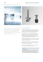
Hygienic Valves and Components Introduction Hygienic Valves and Components The components of GEA Tuchenhagen are based on future-oriented company and product concept principles that include an obligation to economic viability, sustainability and service. Your investment pays off GEA Tuchenhagen hygienic valves and components help you to achieve considerable cost savings. The valve concepts with a variable structure and the efficient control technology provide both low purchase costs and low energy consumption. The design of the valves and individual components without dead space satisfies the...
Open the catalog to page 10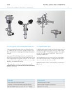
Hygienic Valves and Components GEAIntroduction Hygienic Valves and Components You score points with environmental protection Lower consumption of energy, water and chemicals means less pollution for the environment. GEA Tuchenhagen meets these requirements by complying with binding international standards. As a user of GEA Tuchenhagen products, you benefit from proven environmentally-friendly production processes, as well as the high standards for hygienic processing and care of your products. This makes a significant contribution to protecting the global environment and climate. With our products,...
Open the catalog to page 11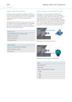
Hygienic Valves and Components Overview Hygienic valves and components Sealing according to the VARIVENT® principle Hygienic valves and components are suitable for CIP/SIP, easy to maintain, offer reliable function and represent a significant factor in consistent product quality. Low costs with operation, maintenance and service ensure economical system productivity. The hygienic valves and components offered by GEA Tuchenhagen are characterized by special seal technology. A metallic stop results in defined seal deformation, ensuring long seal life. This allows for more time to pass between required...
Open the catalog to page 12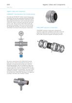
Hygienic Valves and Components · 13 Overview Hygienic valves and components VARINLINE® instrumentation free of dead pockets The trademark VARINLINE® includes control and measuring instruments that meet the requirement of being CIP/SIP-able, thus enabling cleaning and sterilization without the need for dismantling. The instruments can be cleaned and sterilized without any residue in automatic cleaning and sterilizing process cycles. The core piece of the in-line control and measurement technology is the process connection fitting, the VARINLINE® housing. It is mainly an in-line housing with double...
Open the catalog to page 13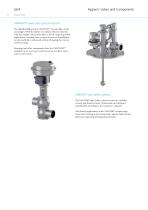
Hygienic Valves and Components Overview VARIVENT® valves with special function The high flexibility in the VARIVENT® system offers many advantages. With the ability to combine all basic elements with one another, the system offers a broad range of possible applications. Existing valve systems in process installations can be modified or enhanced without changing the current system concept. Housings and other components from the VARIVENT® modular kit are used e.g. in control valves, overflow valves and vacuum valves. VARITOP® tank safety systems The VARITOP® tank safety system consists of a modular...
Open the catalog to page 14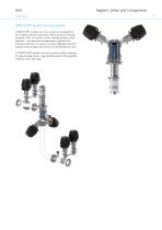
GEA Overview VARICOVER® product recovery systems VARICOVER® product recovery systems are designed for use in fully automatic operations with maximum cleaning demands. They are used to recover valuable products from pipelines – an important consideration to optimize the economic efficiency of a process system. Pigging pushes the product from the pipes and returns it to the production cycle. A VARICOVER® product recovery system usually comprises of a pig cleaning station, a pig catching station with propellant medium valves and a pig. Hygienic Valves and Components ·
Open the catalog to page 15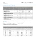
Hygienic Valves and ComponentsAvailable nominal widths for valve series Nominal width DN 10 15 25 40 50 65 80 100 125 150 162
Open the catalog to page 16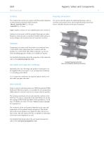
Hygienic Valves and Components · 17 Technical Data Surfaces Housing connections The standard for surfaces in contact with the product depends on the particular nominal width standard: • Metric, inch OD, ISO: R a ≤ 0.8 μm • Inch IPS: R a ≤ 1.2 μm For valves with the option of combining housings, such as overflow and control valves, the clamped housing connection forms a flexible selection of the port orientation. Higher-quality surfaces are an available option (see section 7). Surfaces not in contact with the product (housing) are matte blasted or metal ground as standard. Detailed information...
Open the catalog to page 17All GEA Wiegand catalogs and technical brochures
 GEA POWDEREYE® 2025
4 Pages
 GEA LYOPLUS™
6 Pages
 Evaporation Technology 2009
24 Pages
 Wiegand Steam Jet Cooling Plants
16 Pages
 Jet Vacuum Systems
8 Pages
 Membrane Filtration
12 Pages
 Ethanol production
2 Pages
 perfect brewing solutions
6 Pages
 GEA Wiegand Company Brochure
24 Pages
 Bioethanol Technology
16 Pages
 Distillation Technology
16 Pages


Archived catalogs
 GEA Wiegand Services
4 Pages
 GEA in brewing
6 Pages
 GEA ProductGuide Brewing
24 Pages


- Industrial pump
- Pump with electric motor
- Stationary pump
- Seawater pump
- Compressor stage
- Stainless steel pump
- Air compressor
- Positive-displacement compressor
- Stationary compressor
- Dynamic agitator
- Suction pump
- Transfer pump
- Industrial compressor
- Chiller
- Electrically-powered compressor
- Grinding mill
- Reciprocating piston compressor
- Drying system