
- Catalogs
- GE Vernova
- Masoneilan Butterfly Control Valves


- Products
- Catalogs
- News & Trends
- Exhibitions
Masoneilan Butterfly Control Valves

Masoneilan Butterfly Control Valves
The manual provides comprehensive instructions for the installation, operation, and maintenance of the Masoneilan 36005 Series High Capacity Control Ball Valves. It emphasizes adherence to safety protocols and the use of Masoneilan replacement parts, targeting trained professionals. A numbering system is included for valve configuration identification.
Safety warnings are categorized as DANGER, WARNING, and CAUTION to prevent personal injury and equipment damage. Compliance with these notices is crucial for safe operation.
- General: Carefully unpack the valve and record serial data for future reference.
- Pipeline Mounting: Clean the valve and pipeline of foreign materials before installation. Install the valve with the flow direction pushing the seal ring against the ball, preferably with the ball opening upward for slurry applications.
Detailed instructions are provided for maintaining various subassemblies of the valve, including the bracket, body, actuator, and handwheel. The use of genuine parts is emphasized, with diagrams for reference.
The document includes figures illustrating the numbering system, general assembly, actuator sizes, and handwheel details. Tables provide parts lists for different valve components.
GE warrants the products to be free from defects for one year from the date of shipment, provided they are used according to recommended guidelines. Product design or specifications may change without notice.
- Flange bolt lengths are non-standard on the inlet and standard on the outlet side.
- Bolting should be tightened evenly in a crisscross fashion to ensure even pressure on the seal ring.
- The linkage of the 36005 V-Max valve is pre-adjusted at the factory and requires no further adjustment.
- Insulation of the valve body should not cover the valve bonnet.
- Air piping must be adequately sized to provide the regulated supply pressure as specified on the nameplate.
- Use 1/4" O.D. tubing for air lines, or 3/8" O.D. tubing if the supply air line exceeds 25 feet.
- The actuator has a 1/4" NPT instrument air port on the upper case.
- Before changing actuator position or performing maintenance, isolate the valve, vent process pressure, and shut off air supply and signal air lines.
- It is recommended to remove the valve from the pipeline prior to maintenance work.
- Keep hands and tools away from the segmental ball to avoid injury.
- Actuator positioning should be done before installing the valve in the pipeline.
- To change actuator position or valve action, follow the disassembly and reassembly instructions provided.
- Ensure proper alignment of the lever on the shaft for correct valve operation.
- Valve action should be changed before installation to ensure the ball plug is fully closed when the actuator is in the proper position.
- Follow specific instructions for different models and sizes to change valve action.
- Do not exceed maximum air supply pressure.
- Ensure rotation of the actuator does not exceed 90 degrees to prevent damage.
- Keep hands clear of actuator stem and linkage during operation.
- Bracket Subassembly (Model 33, Sizes B & C): Detailed steps for disassembly and reassembly, including the removal and replacement of various components like the actuator, handwheel, and indicator arm.
- Bracket Subassembly (Model 33, Size AC): Similar procedures for size AC, with specific instructions for handling the actuator and handwheel assembly.
- Body Subassembly: Instructions for packing maintenance, including disassembly and reassembly of packing rings, are provided. Avoid overtightening to prevent excessive friction.
- Seal Ring Maintenance: Procedures for different types of seal rings (MN-7, Standard Metal, and Heavy Duty Metal) are detailed, including removal, inspection, and reinstallation steps.
- Ball Plug Maintenance: Steps for disassembling the ball plug, including the removal of the bracket and seal assembly, are included.
The document recommends using specific lubricants like Dow-Corning 111® and 321® for seal and ball plug maintenance. Proper alignment and securing of components during reassembly are crucial for optimal valve operation.
- Disassembly: Involves removing nuts, flanges, shafts, and bushings. Key steps include using a rod to push out components if they are stuck and inspecting parts for damage.
- Reassembly: Requires cleaning and lubricating components, replacing bushings and gaskets, and ensuring proper alignment and engagement of parts. Special attention is given to the application of dry graphite lubricant for certain seal rings.
- Disassembly: Emphasizes safety due to spring tension. Steps include isolating the valve, removing air supply, and carefully loosening tension nuts to avoid injury.
- Reassembly: Involves aligning components, installing tension nuts and bolts, and ensuring proper sealing of the diaphragm. A criss-cross tightening pattern is recommended to avoid overtightening.
- Disassembly: Involves removing retaining clips and pins, checking for wear, and cleaning components.
- Reassembly: Includes installing washers, lubricating components, and ensuring correct assembly without overtightening.
- Disassembly: Focuses on safely relieving actuator pressure and removing diaphragm components while maintaining tension bolt security.
- Reassembly: Ensures clean sealing surfaces, correct alignment of diaphragm and bolt holes, and even tightening of tension nuts to avoid injury.
The document stresses the importance of safety precautions, proper lubrication, and even tightening of components to ensure effective maintenance and operation of the valve system.
Catalog excerpts

Masoneilan* High Capacity Control Ball Valve Instruction Manual GE Data Classification : Public
Open the catalog to page 1
b | GEOil&Gas © 2014 General Electric Company. All rights reserved.
Open the catalog to page 2
THESE INSTRUCTIONS PROVIDE THE CUSTOMER/OPERATOR WITH IMPORTANT PROJECT-SPECIFIC REFERENCE INFORMATION IN ADDITION TO THE CUSTOMER/OPERATOR’S NORMAL OPERATION AND MAINTENANCE PROCEDURES. SINCE OPERATION AND MAINTENANCE PHILOSOPHIES VARY, GE (GENERAL ELECTRIC COMPANY AND ITS SUBSIDIARIES AND AFFILIATES) DOES NOT ATTEMPT TO DICTATE SPECIFIC PROCEDURES, BUT TO PROVIDE BASIC LIMITATIONS AND REQUIREMENTS CREATED BY THE TYPE OF EQUIPMENT PROVIDED. THESE INSTRUCTIONS ASSUME THAT OPERATORS ALREADY HAVE A GENERAL UNDERSTANDING OF THE REQUIREMENTS FOR SAFE OPERATION OF MECHANICAL AND ELECTRICAL EQUIPMENT...
Open the catalog to page 3
Contents Important : Safety Warning1 1.0 Introduction Numbering System . . . . . . . . . . . . . . . . . . . . . . . . . . . . . . . . . . . . . . . . . . . . . . . . . . . . . . . . . . . . . . . . . . . . . . . . . . . . . . . . . . . . . . . . 2 2.0 Installation 2.1 General . . . . . . . . . . . . . . . . . . . . . . . . . . . . . . . . . . . . . . . . . . . . . . . . . . . . . . . . . . . . . . . . . . . . . . . . . . . . . . . . . . . . . . . . . . . . . . . . 4 2.2 Pipeline Mounting . . . . . . . . . . . . . . . . . . . . . . . . . . . . . . . . . . . . . . . . . . . . . . . . . . . . ....
Open the catalog to page 4
WARNING Safety Information Important - Please Read Before Installation Masoneilan 36005 Series instructions contain DANGER, WARNING, and CAUTION labels, where necessary, to alert you to safety related or other important information. Read the instructions carefully before installing and maintaining your control valve. DANGER and WARNING hazards are related to personal injury. CAUTION hazards involve equipment or property damage. Operation of damaged equipment can, under certain operational conditions, result in degraded process system performance that can lead to injury or death. Total compliance...
Open the catalog to page 5
1.0 Introduction The following instructions are designed to assist maintenance personnel in performing most of the maintenance required on the 36005 V-Max* valve and if followed carefully will reduce maintenance time. GE Masoneilan has highly skilled Service Engineers available for start-up, maintenance and repair of our valves and component parts. In addition, regularly scheduled training programs are conducted to train customer service and instrumentation personnel in the operation, maintenance and application of our control valves and instruments. Arrangements for these services can be made...
Open the catalog to page 6
V-Max Valves Actuator Model 33, Size AC Actuator Position in Relation to Valve Body Numbering System: 1 to 8 Actuator Model 33, Sizes B and C © 2014 General Electric Company. All rights reserved. Masoneilan 36005 Series High Capacity Control Ball Valves | 3
Open the catalog to page 7
2.1.1 Unpack valve carefully to avoid damage to valve, accessories, or tubing. 2.1.2 Record all valve and accessory serial plate data for future reference. Always provide serial and model numbers when ordering spare parts. CAUTION Do not remove button head screw (9) and washer (10) during installation. The function of these parts is to hold the retainer (3) and seal ring (8) in place and should be removed only when the valve is to be disassembled for maintenance (Figure 2). A. Before installing the valve in the line, clean pipe and valve of all foreign materials such as welding chips, scale,...
Open the catalog to page 8
CAUTION CAUTION Before proceeding determine valve action (air to open/air to close), refer to the appropriate figure (Figure 10 to open, Figure 11 to close). To obtain proper alignment, the lever must be oriented on the shaft so that the slot in the end of the shaft and arrows or indicator lines are aligned as shown; with the ball in the closed position, the distance between the top of the bracket and the top of the pivot pin must be as shown. G. lide lever (32) and lever arm (64) back onto shaft in S desired position. Slide indicator arm (35) back onto shaft. Align bracket and slide back onto...
Open the catalog to page 9
CAUTION removal of the bracket is not required. CAUTION Before proceeding determine valve action (air to open/air to close). G. lide lever (32) back onto shaft in desired position. S Slide indicator arm (35) back onto shaft. Align bracket and slide back onto mounting studs (26) and packing flange studs (25). Replace mounting stud nuts (24) and washers (18). Slide packing flange (23) back onto packing flange studs (25) and replace packing flange stud nuts (24). H. Remount actuator onto housing and replace actuator mounting hex nuts (75) and washers (76). Position lever (32) so that rod end bearing...
Open the catalog to page 10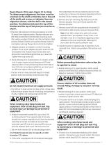
figure (Figure 10 to open, Figure 11 to close). To obtain proper alignment, the lever must be oriented on the shaft so that the slot in the end of the shaft and arrows or indicator lines are aligned as shown; with the ball in the closed position, the distance between the top of the bracket and the top of the pivot pin must be as shown. F. lip lever (32) and lever arm (64) and replace on shaft F 90 away from original position. Replace indicator arm (35). Slide bracket back onto bracket mounting studs (26), replace washers (18) and nuts (24) and tighten. Slide packing flange (23) back over packing...
Open the catalog to page 11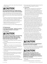
CAUTION adjustment as noted in step I above. Return ball plug (2) to open position. CAUTION Do not exceed maximum air supply pressure. Keep hands clear of actuator stem and linkage. Loosen rod end bearing locknut (93) and adjust rod end bearing (94) so that holes in lever (32) and rod end bearing (94) line up. Insert pivot pin (39) and replace retaining rings (40). I. For both air to open and air to close action, stroke valve fully to ensure proper closure of ball plug and operation of valve. It may be necessary to readjust rod end bearing slightly by loosening locknut and rotating stem. DANGER...
Open the catalog to page 12
replace clevis pin (66), retaining clips (63), and pivot pins (72). H. et and lock indicator arm (35) to indicate plug position. S I. heck that handwheel operates valve through full range C of travel. There is a 1/2" adjustment available at the end of the handwheel extension. Retract handwheel, remove end cap (51) and cap screw (55B). Rearrange stop (55A) and/or spacer (55C) to obtain desired extension. 3.2 Bracket Subassembly – Model 33, size AC only. Refer to section 3.1 for sizes B & C 3.2.1 Disassembly CAUTION When disconnecting actuator rod end bearing from shaft arm, the ball is likely...
Open the catalog to page 13All GE Vernova catalogs and technical brochures
 LM6000
1 Page
 STEAM POWER SERVICES CATALOG
94 Pages
 NUCLEAR POWER PRODUCT CATALOG
28 Pages
 STEAM POWER PRODUCT CATALOG
61 Pages
 2018 POWER SERVICES CATALOG
111 Pages
 7E POWER PLANTS
1 Page
 LMS100®
7 Pages
 LMS100 POWER PLANTS
1 Page
 LM2500 POWER PLANTS
1 Page
 LM6000 POWER PLANTS
1 Page
 6B POWER PLANTS
2 Pages
 9E & GT13E2 POWER PLANTS
2 Pages
 6F POWER PLANTS
2 Pages
 9F.04, 9F.05, 9F.06
2 Pages
 1483_1112.indd
1 Page
 1212_1012
12 Pages
 Powering the world 2016
72 Pages
 raising the bar
8 Pages
 Waukesha* gas engines
12 Pages
 6 F. 01 Gas Turbine
4 Pages
 9HA.01 / .02 GAS TURBINE
2 Pages
 Dresser? Turbine Meters
8 Pages
 HSR line
6 Pages
 CNG In A Box? system
16 Pages
 Becker? T-Ball? Anti-Surge Valve
12 Pages
 Becker V0 Control Valves
12 Pages
 Ajax? E-565 Gas Engine
2 Pages
 7E.03 HDGT
15 Pages
 Baghouse Accessories
12 Pages
 Fabric Filter Bags & Cages
2 Pages
 GE10 15 ppm combustor
3 Pages
 GE10-1 Gas Turbine
8 Pages


Archived catalogs
 GE10-2 15 ppm combustor
3 Pages
 Heavy Duty Gas Turbine Products
24 Pages
 Gas Turbines Catalog
31 Pages
 GE10 Gas Turbine
6 Pages
 Frame 6 Gas Turbine
3 Pages
 Product Structuring
5 Pages
 7HA.01 / .02 GAS TURBINE
2 Pages
 18900_5_15
8 Pages
 69663_aftermkt_bro
4 Pages
 66535_reman_bro_redo_FINAL
6 Pages
 Reciprocating Engines
2 Pages
 7F POWER PLANTS
2 Pages
 7HA gas turbine
4 Pages
 9HA Gas turbine
4 Pages
- Heat exchanger unit
- Liquid/liquid heat exchanger
- Tubular heat exchanger
- Stainless steel heat exchanger
- Steam generator
- Three-phase alternator
- GE Vernova power generation turbine
- GE Vernova gas turbine
- Condenser
- Water/water heat exchanger
- Cooled condenser
- GE Vernova combined-cycle turbine
- Steam turbine
- Industrial steam generator
- Aeroderivative turbine
- Vertical steam generator
- Steel condenser
- Gas steam generator
- Single-shaft turbine
- Horizontal steam generator