MPM
1 /4Pages

MPM
1 /4Pages
Catalog excerpts

Additional, continuous metering of motors via the 269 or 269 Plus Motor Protection System. ■ Provides additional motor metering functionality to a 269 or 269 Plus ■ Complete metering & monitoring - High accuracy, mid- range Power Quality with many advanced features ■ Ease of use, program and set up - Includes EnerVista setup and metering software ■ Cost Effective Access information - Through Modbus RTU protocol over RS485 communication capability, allows easy integration to EnerVista or third party systems ■ Continuous metering of motors via a 269 Motor Protection System Additional protection with 269 combination ■ kvar limit ■ Voltage phase reversal ■ Under/overvoltage alarm/trip ■ Power factor alarm/trip (lead/lag) ■ MPM communication failure alarm Overload (15 selectable curves) Monitoring Data displayed by 269 ■ 3 phase voltage ■ Average voltage ■ Power factor ■ Real power (kW) ■ Reactive power (kvar) ■ Power consumption (MWh) ■ Frequency (Hz) Inputs and Outputs ■ Four 0-1 mA (A1 option) or 4-20 mA (A20 option) outputs of: ■ Average current (Amps) ■ 3 phase real power (kW) ■ 3 phase reactive power (kvar) ■ Power factor ■ Fail-safe form-C dry contact output relay ■ VT wiring configuration selection User Interface ■ RS485 serial port GE Consumer & Industrial Multilin EnerVista 1_ Device Health and r7,d-iSecurity Reporting VIEWPOINT Software
Open the catalog to page 1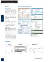
MPM Motor Protection Metering System Features Mounting Versatility Due to the compact size of the MPM, it is especially practical for applications where mounting space is limited. The MPM is a "black box" unit which uses serial communications to transmit/ receive data to and from the 269/269 Plus. Therefore, it can be mounted inside the switchgear or in a location where there is more room available. A single twisted pair communication wire is routed to the 269/269 Plus. To obtain optimum accuracy, metering class CTs should be employed. In applications where mounting space and/or cost is an issue,...
Open the catalog to page 2
MPM Motor Protection Metering System Typical Wiring ALTERNATIVE CT/VT CONNECTIONS OBSERVE CT & VT POLARITY 3 WIRE DELTA/60° VOLTAGE 2 VTs Perferrred 4 wire configuration SW1 = CLOSED SW2 = OPEN USE HEAVY GAUGE WIRE SWITCHGEAR GROUND BUS Multilin MPM Motor Protection Metering System ANALOG OUT TO PLCs, RTUs METERs OR SCADA SYSTEM ETC. NOTES: 1) Relay contact state shown with control power not applied. A CAUTION: USE HRC FUSES FOR VT PRIMARY TO ENSURE ADEQUATE INTERRUPTING CAR4CITY.
Open the catalog to page 3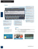
MPM Motor Protection Metering System Features MUUXJN VERSON: ANALOG OUTPUTS 4 isolated 0-1mA(A1 option) or 4-20 mA (A20 option) outputs assigned to average current, real power, reactive power and power factor. SWITCH INPUTS MAXIMUM CONTACT RATING OUTPUT RELAY One form-c failsafe output relay AC/DC CONTROL POWER Universal control power 90-300 VDC/70-265 VAC (HI option) 20-60 VDC/20-48 VAC (LO option) CT INPUTS: 3 isolated phase CT inputs 1 Amp or 5 Amp secondary COMMUNICATIONS RS485, isolated, communications port to transmit and receive data from the 69 FUSE ACCESS Control power fuse accessible...
Open the catalog to page 4All GE Steam Turbines catalogs and technical brochures
 NUCLEAR POWER PRODUCT CATALOG
28 Pages
 STEAM POWER PRODUCT CATALOG
61 Pages
 Steam Turbine STF-600 Series
2 Pages
 2018 STEAM POWER PRODUCT CATALOG
65 Pages
 Powering the World
24 Pages
 Steam Turbine STF-600 Series
2 Pages
 RECIPROCATING ENGINES
4 Pages
 19065_275GL_BRO_11_14.INDD
8 Pages
 18900_5_15.INDD
8 Pages
 STEAM TURBINES A450 / D400
2 Pages
 STEAM TURBINES A200 / D200
2 Pages
 ESBWR
ESBWR2 Pages
 Turboexpander-Generators
4 Pages
 Turboexpander-Compressors
5 Pages
 Onshore Wind Brochure
4 Pages
 NEW PIPE RECOVERY BROCHURE
16 Pages
 NEW OPEN HOLE BROCHURE
16 Pages
 Industrial Steam Turbines
28 Pages


