SPM
1 /8Pages

SPM
1 /8Pages
Catalog excerpts

Synchronous motor protection system Starting protection, synchronization and control for synchronous motors Key Benefits • Complete asset monitoring - Field Winding temperature and statistical data • Access to information - RS485 Communications port and Modbus RTU Protocol • Improve uptime of auxiliary equipment - Through I/O monitoring Applications • Starting, synchronizing and protection of collector-ring or brushless-type synchronous motors Features Protection and Control User Interface • Field application • 40 Character backlit display for easy viewing of settings and actual values • DC field current loss, exciter current loss, DC field voltage check • PF regulation, reluctance torque synchronizing • Function keys allow programming of settings and viewing of measured values • Protects motor during start up and in the event of asynchronous operation • Squirrel cage winding overheating protection • Automatic phase rotation correction • Auto-loading and incomplete sequence • Regulator tuning mode • True RMS metering with DFT filtering • Optional power factor regulator with adjustable settings • Power factor & pull out protection (Optional) • Speed dependent squirrel cage overload protection • Motor restart protection Monitoring and Metering • Motor power factor • RS485 Serial Communications • Optional Ethernet communications using Multinet Serial to Ether converter EnerVistaTM Software • State of the art software for configuration and commissioning GE Multilin products • Document and software archiving toolset to ensure reference material and device utilities are up-to-date • EnerVistaTM Integrator providing easy integration of data in the SPM into new or existing monitoring and control systems • DC excitor amps and voltage • AC Current • Exciter field resistance • Motor run
Open the catalog to page 1
SPM Synchronous Motor Protection System This feature trips the motor when field current drops below the programmed setpoint after the motor has synchronized. To utilize this feature a DCCT and Field Current Calibration Module must be ordered with the SPM. Reduced Voltage Starting An important motor protection function is preventing squirrel cage winding overheating during motor starting. For brushless motors squirrel cage protection is derived from stator current inputs. Protection characteristics are shown in the following graph and the thermal limit is defined by the Stall Time and Locked Rotor...
Open the catalog to page 2
SPM Synchronous Motor Protection System The Incomplete Sequence protection will issue a trip if the SPM detects that the motor has not reached synchronous speed within the programmable time delay. Exciter DC Voltage Protection Exciter voltage protection is available by connecting the exciter output to the SPM terminals VE+ and VE- through a voltage divider network (VDN). This is used on equipment where the exciters are energized prior to motor startup. Field Winding Overtemperature Option This function emulates a resistance temperature device (RTD) on the field windings. As the ratio of field...
Open the catalog to page 3
SPM Synchronous Motor Protection System Field Voltage Input: closes when the motor reaches full voltage during a reduced inrush start. Control Power: The SPM has an AC power supply with a range from 85 to 265 VAC. If control voltage excursions occur outside this range, an external stabilizing ansformer should be used in conjunction with optional separate power factor reference voltage inputs. The induced field voltages VF+ and VF- are monitored through their connection to the external discharge resistor via the VDN, providing instantaneous value of motor slip. Exciter Voltage Input: The VE+ and...
Open the catalog to page 4
SPM Synchronous Motor Protection System The EnerVista™ Suite is an industry leading set of software programs that will simplify every aspect of using the SPM relay. Tools to monitor the status of your motor, maintain your relay, and integrate information measured by the SPM into HMI or SCADA monitoring systems are available. EnerVista™ Launchpad EnerVista™ Launchpad is a powerful software package that provides users with all of the setup and support tools needed for configuring and maintaining GE Multilin products. Launchpad allows configuring devices in real-time by communicating using serial,...
Open the catalog to page 5
SPM Synchronous Motor Protection System Typical Wiring TYPICAL BRUSHLESS MOTOR CONNECTION T2 SYNC MOTOR NOMENCLATURE FIELD CURRENT CALIBRATION MODULE DIRECT CURRENT CT MAIN CONTACTOR OVERLOAD RELAY MOTOR TERMINALS OPTIONAL ACCESSORIES VOLTAGE DIVIDER NETWORK (VDN) PHASE CURRENT INPUT NOTES: Motor Protection 1) Relays shown with no control power applied to relay 2) *Trip Relay closed during normal operation GE Multilin FIELD CONTACTOR TYPICAL COLLECTOR RING MOTOR CONNECTION SYNC MOTOR FIELD DISCHARGE RESISTOR FILTER GROUND FIELD CONTACTOR VOLTAGE DIVIDER NETWORK (VDN) PHASE CURRENT INPUT CONTROL...
Open the catalog to page 6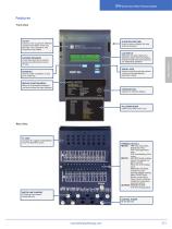
SPM Synchronous Motor Protection System Features Front View GE KEY Used to enter or exit the different modes of the SPM. These are Standby, Test, Statistics, and Programming modes. QUICK RELEASE TABS Used to remove display for easy access to drawout. LOCKING PROVISION A wire lead seal can be used to prevent unauthorized removal of relay. Motor Protection LCD DISPLAY Backlit 32 character display for setpoints, actual values and status. Programmable auto scan sequence for unattended operation. SCROLL KEYS Used to scroll through the various menus and change setpoint parameter values. ENTER KEY Used...
Open the catalog to page 7
SPM Synchronous Motor Protection System Technical Specifications Motor Protection OUTPUTs PF analog output Type: Active Output: 0 – 10 VDC max @ RL 1K (min load) Accuracy: ±10% (0.1 v) Isolation: 36 V VpK relay contactS Type: FAR, TRP Form A FCX Form C Rated load: 10 A AC continuous NEMA A300 1 A DC continuous NEMA R300 Break: 10A 250 VAC or 30 VDC Max operating voltage: 250 VAC POWER SUPPLY control power Input: 85 – 265 VAC @ 48 – 60 Hz Power: 10 VA nominal Holdup: 100 ms typical @ 120 VAC environmentAL Humidity: 0 – 95% non-condensing Operating temperature: -20° C to +70° C Storage temperature:...
Open the catalog to page 8All GE Grid Solutions catalogs and technical brochures
 Static Var Compensator Solutions
12 Pages
 Kelman TRANSFIX
2 Pages
 Kelman MINITRANS
2 Pages
 MIG
MIG3 Pages
 DTR
DTR4 Pages
 TOV
TOV3 Pages
 MDS SD Series
4 Pages
 MIC
MIC2 Pages
 Multilin F60
9 Pages
 Model PT7-1-150 & PT7-1-200
2 Pages
 Models PT7-2-150 & PT7-2-200
2 Pages
 Model PT6-2-125
2 Pages
 Model PT6-1-125
2 Pages
 Models PTW5-1-110&PTW5-2-110
2 Pages
 Models PTG4-1-75 & PTG4-2-75
2 Pages
 Models PTW3-1-60 & PTW3-2-60
2 Pages
 Models PTG3-1-60 & PTG3-2-60
2 Pages
 Models PT3-1-45 & PT3-2-45
2 Pages
 Model 3PT3-60
2 Pages
 MIG II
8 Pages
 Model JVW-110C
2 Pages
 Model JVW-5AC-1
2 Pages
 Model JVW-5C
2 Pages
 Multilin T60
9 Pages
 Multilin 489
9 Pages
 Multilin™ D25
8 Pages
 Multilin D485
1 Page
 Multilin P485
1 Page
 MultiNet
3 Pages
 iNET-II
4 Pages
 MDS™ iNET 300
2 Pages
 MDS iNET 900®
2 Pages
 Multilin™ PQM II
8 Pages
 Multilin L90
10 Pages
 COSI
COSI2 Pages
 Reason DR60
4 Pages
 Multilin 850
4 Pages
 G650
G6508 Pages
 Hydran M2
2 Pages
 MultiLink ML3000 Series
12 Pages
 TN1U
TN1U4 Pages
 JungleMUX SONET Multiplexer
4 Pages
 Multilin™ MM200
8 Pages
 Multilin™ MM300
8 Pages
 Multilin 339
16 Pages
 Multilin 469
10 Pages
 Multilin A60
6 Pages
 Multilin 350
16 Pages
 Multilin F650
12 Pages
 Multilin 750/760
10 Pages
 F35
F358 Pages
 345
34512 Pages
 745
7458 Pages
 Multilin G30
9 Pages
 Transmission Overview
9 Pages
 Air-Core Reactors
8 Pages
 Multilin HardFiber System
14 Pages
 Multilin UR & URPlus
18 Pages
 Multilin C30
6 Pages
 Voltage Regulators
16 Pages
 g3 Technology
2 Pages
 Rectifier
4 Pages
 RMIO
RMIO2 Pages
 MiCOM Agile P54A/B
2 Pages
 MultiSync™ 100
6 Pages
 Multilin G60
9 Pages
 Multilin D400
12 Pages
 GL 107X
2 Pages
 Disconnectors
12 Pages
 CGVB-05
2 Pages
 KOTEF
KOTEF4 Pages
 Adjustable Height Sub Base
2 Pages
 HV Transmission Solutions
8 Pages
 FK
FK4 Pages
 B65
B654 Pages
 Safe-NET Network Transformer
8 Pages
 Green Power Transformers
4 Pages
 COSI-RogoFlex
2 Pages
 Grid-GA-L3-COSI_CEVT
2 Pages
 P50 Agile P154 / P253
4 Pages
 MiCOM Agile P24x
8 Pages
 239 Motor Protection
8 Pages
 Power Transformers
8 Pages
 smorb
smorb3 Pages
 MIF II
8 Pages
 SR family
2 Pages
 735/737
4 Pages
 hid
hid2 Pages
 dtp
dtp5 Pages
 IEC Oil Filled & SF
12 Pages
 Gas Insulated Switchgear
24 Pages
 Multilin UR & UR Plus
18 Pages
 M60
M608 Pages
 MDS Orbit Platform Brochure
12 Pages


Archived catalogs


- GE Vernova transformer
- GE Vernova dry transformer
- Digital I/O
- IO module
- Analog I/O
- Capacitor
- Digital IO module
- Circuit breaker
- Protection relay
- Current transformer
- Isolator switch
- Signal amplifying integrated circuit
- IEC transformer
- Encapsulated transformer
- Power transformer
- Single-phase transformer
- Industrial communication router
- Analog IO module
- GE Vernova industrial transformer
- Serial I/O