- Catalogs
- GE Grid Solutions
- Safe-NET Network Transformer
Safe-NET Network Transformer
1 /8Pages

Safe-NET Network Transformer
1 /8Pages
Catalog excerpts

Safe-NET Network Transformer Safely and reliably supply power to secondary grid systems Utilities provide safe and reliable electrical service to their end customers. In large metropolitan areas with densely populated cities, utilities provide this service over secondary network distribution systems. These network systems are largely underground, therefore the network transformers that support these systems are a vital and critical part of the electrical infrastructure. GE's Safe-NET network transformers are the safest transformers available in the industry for secondary network applications. Safe-NET network transformers are designed to supply power to the network bus and are capable of handling significant short-term overload conditions in this application. GE's exclusive transformer tank design features patented tank technology that minimizes the danger from a transformer rupture event, mitigating its impact to adjacent assets and public safety. Key Benefits • Increased Public Safety Patented tank design significantly reduces risk to the public and property that may be in close proximity to the transformer location when a high-energy event occurs • Increased Operational Safety and Performance Tank design is capable of withstanding in excess of 11 mega joules of energy, exceeding the pressure requirements laid out in the IEEE C57.12.40 standard • Validated Risk Mitigation and Peace of Mind Independent, 3rd party validation by KEMA of tank design and response to high energy events • Exceptional Product Durability and Reliability The zinc epoxy primer and black epoxy top-coat paint utilized is superior to any other paint solution used today, passing 10,000-hour salt-spray certification tests • Eco-friendly with Low Carbon Footprint Available high flash point vegetable-based insulating oil reduces environmental impact Applications GE's Safe-NET Network Transformers are used in applications where safety, reliability, service continuity and minimum maintenance are the key objectives, including: • Underground metropolitan vault applications • Office towers, skyscrapers • Government, commercial, institutional and • Vault applications with occasional/continuous industrial facilities submersion GE's Network Transformers can also be applied to non-network applications where superior sealing and corrosion protection are of primary importance. These non-network applications also include intertie [step] transformers for interconnecting two different voltage systems. Exclusive Tank Design • Patented tank technology provides a safe and controlled failure-mode during high energy events • Exclusive transformer tank design and patented tank technology minimizes the danger from an "end-of-life" event resulting from a high-energy fault • Best in class corrosion resistant paint minimizes maintenance over long haul and increases life cycle of transformer Exceeds Industry Standards • The Safe-NET tank design exceeds the tank pressure requirements laid out in the ANSI®/ IEEE® C57.12.40 standard • Patented tank design can contain most high energy events • Best in class product lifecycle including an installed base with 85+ years of service 3rd Party Validated • GE's units are capable of withstanding in excess of 11MJ of energy, confirmed by KEMA® testing • Tested and certified to the highest North American standard for ground-level seismic levels, CBC-2013 section 1705A.12 and IBC 2012 section 1705.12, tested to (an acceleration value of) SDS = 2.5 • Superior zinc epoxy primer and black epoxy top coat paint with 10,000 hour salt-spray certification
Open the catalog to page 1
Low Voltage Secondary Network Overview Since the 1920’s, the low voltage secondary network has been an effective method of serving dense loads like office buildings and downtown areas. The basic design of the network system ensures high reliability and dependable power quality. The network system’s reliability comes from having multiple sources. The grid network in the diagram below shows that the network system is fed by multiple transformers with multiple sources back at the substation. This means that the loss of any single transformer or line will not have an effect on the load served by...
Open the catalog to page 2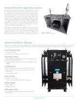
Network Transformer Application Overview The transformers that are used in these low voltage secondary networks are referred to as network transformers. Space limitations in urban environments result in the network transformers being installed in various applications such as indoor and outdoor vaults as well as inside buildings. All of these applications will typically have these network transformers in close proximity to pedestrian and other traffic. The image to the right represents a typical application for a network transformer, where it is placed in an underground vault under a sidewalk,...
Open the catalog to page 3
GE’s Network Transformers High Fault Energy Tank Design Challenge Arcing, corrosion and overloading are the three key drivers for end-of-life tank events in network transformers. Given the network transformers placement in underground vaults, which very often are below sidewalks, service events in the field pose a risk of injury to individuals in close proximity as well as additional asset damage and power outages. Traditional network transformers do not have the same capacity to contain high energy events which can often cause undesired collateral damage resulting from an uncontrolled tank rupture....
Open the catalog to page 4
Network Transformer Features Switch-box with cover removed (primary switch is exposed) Primary switch contacts and rotor Switch-box liquid-level gauge and filling provision Main tank thermometer Main tank liquid level gauge
Open the catalog to page 5
STANDARD OFFERING OPTIONAL OFFERING Power Ratings 300kVA through 2500kVA (three-phase only) • Up to 3000kVA for step-down/intertie designs • Special kVA ratings to maximize kVA/in3 in the vault Voltage Ratings • Primary Voltages from 2.4kV through 34.5kV • Dual Voltage (series multiple) primary • Primary taps per C57.12.40 • Special Primary taps • Secondary Voltages from 208GrdY/120 to 480GrdY/277 • Secondary Voltages up to 4.33kV (60kV BIL rating) BIL Ratings • Primary BIL ratings 60kV to 200kV BIL Non-standard BIL ratings • Secondary BIL rating of 30kV BIL Thermal Ratings Thermal...
Open the catalog to page 6All GE Grid Solutions catalogs and technical brochures
 Static Var Compensator Solutions
12 Pages
 Kelman TRANSFIX
2 Pages
 Kelman MINITRANS
2 Pages
 MIG
MIG3 Pages
 DTR
DTR4 Pages
 SPM
SPM8 Pages
 TOV
TOV3 Pages
 MDS SD Series
4 Pages
 MIC
MIC2 Pages
 Multilin F60
9 Pages
 Model PT7-1-150 & PT7-1-200
2 Pages
 Models PT7-2-150 & PT7-2-200
2 Pages
 Model PT6-2-125
2 Pages
 Model PT6-1-125
2 Pages
 Models PTW5-1-110&PTW5-2-110
2 Pages
 Models PTG4-1-75 & PTG4-2-75
2 Pages
 Models PTW3-1-60 & PTW3-2-60
2 Pages
 Models PTG3-1-60 & PTG3-2-60
2 Pages
 Models PT3-1-45 & PT3-2-45
2 Pages
 Model 3PT3-60
2 Pages
 MIG II
8 Pages
 Model JVW-110C
2 Pages
 Model JVW-5AC-1
2 Pages
 Model JVW-5C
2 Pages
 Multilin T60
9 Pages
 Multilin 489
9 Pages
 Multilin™ D25
8 Pages
 Multilin D485
1 Page
 Multilin P485
1 Page
 MultiNet
3 Pages
 iNET-II
4 Pages
 MDS™ iNET 300
2 Pages
 MDS iNET 900®
2 Pages
 Multilin™ PQM II
8 Pages
 Multilin L90
10 Pages
 COSI
COSI2 Pages
 Reason DR60
4 Pages
 Multilin 850
4 Pages
 G650
G6508 Pages
 Hydran M2
2 Pages
 MultiLink ML3000 Series
12 Pages
 TN1U
TN1U4 Pages
 JungleMUX SONET Multiplexer
4 Pages
 Multilin™ MM200
8 Pages
 Multilin™ MM300
8 Pages
 Multilin 339
16 Pages
 Multilin 469
10 Pages
 Multilin A60
6 Pages
 Multilin 350
16 Pages
 Multilin F650
12 Pages
 Multilin 750/760
10 Pages
 F35
F358 Pages
 345
34512 Pages
 745
7458 Pages
 Multilin G30
9 Pages
 Transmission Overview
9 Pages
 Air-Core Reactors
8 Pages
 Multilin HardFiber System
14 Pages
 Multilin UR & URPlus
18 Pages
 Multilin C30
6 Pages
 Voltage Regulators
16 Pages
 g3 Technology
2 Pages
 Rectifier
4 Pages
 RMIO
RMIO2 Pages
 MiCOM Agile P54A/B
2 Pages
 MultiSync™ 100
6 Pages
 Multilin G60
9 Pages
 Multilin D400
12 Pages
 GL 107X
2 Pages
 Disconnectors
12 Pages
 CGVB-05
2 Pages
 KOTEF
KOTEF4 Pages
 Adjustable Height Sub Base
2 Pages
 HV Transmission Solutions
8 Pages
 FK
FK4 Pages
 B65
B654 Pages
 Green Power Transformers
4 Pages
 COSI-RogoFlex
2 Pages
 Grid-GA-L3-COSI_CEVT
2 Pages
 P50 Agile P154 / P253
4 Pages
 MiCOM Agile P24x
8 Pages
 239 Motor Protection
8 Pages
 Power Transformers
8 Pages
 smorb
smorb3 Pages
 MIF II
8 Pages
 SR family
2 Pages
 735/737
4 Pages
 hid
hid2 Pages
 dtp
dtp5 Pages
 IEC Oil Filled & SF
12 Pages
 Gas Insulated Switchgear
24 Pages
 Multilin UR & UR Plus
18 Pages
 M60
M608 Pages
 MDS Orbit Platform Brochure
12 Pages


Archived catalogs


- GE Vernova dry transformer
- Digital I/O
- IO module
- Analog I/O
- Capacitor
- Digital IO module
- Circuit breaker
- Protection relay
- Current transformer
- Isolator switch
- Signal amplifying integrated circuit
- IEC transformer
- Encapsulated transformer
- Power transformer
- Single-phase transformer
- Industrial communication router
- Analog IO module
- GE Vernova industrial transformer
- Serial I/O