


MIG

MIG
The M Family Digital Machine Protection Relay is equipped with an advanced 16-bit microprocessor, configurable logic, curves, digital I/Os, and LEDs. It includes flash memory for field upgrades, two settings groups, and a drawout case for easy maintenance. The relay supports both AC/DC power supply and can be accessed via a front panel keypad or communication links. It is compatible with M Family systems in half or full 19" racks.
Applications
This relay is designed for protection and control of generators, motors, and transformers. It is compatible with enerVista.com.
Protection and Control
The relay offers thermal image protection, unbalance, overcurrent and undercurrent protection, monitoring and metering, analog/digital oscillography, 24 event recording, and restricted ground fault protection.
User Interfaces
The relay can be configured and monitored using M+PC software. It features front RS232 and rear RS485 ports using ModBus® RTU protocol up to 19,200 bps.
Protection Features
- Thermal Image Unit: Protects against overheating due to negative sequence components.
- Unbalance: Protects against rotor damage from supply voltage unbalance.
- Three-Phase TOC: Offers multiple curve selections for coordination with other equipment.
- Phase IOC Units: Adjustable settings for phase overcurrent protection.
- Ground TOC and IOC: Similar settings as phase units, with options for additional ground sensors.
- Undercurrent: Detects decreases in machine current.
- Starts/Hour and Time To Restart: Limits machine starts to prevent damage.
- Locked Rotor: Protects during long start-ups.
- Restricted Ground Fault: Provides sensitive ground fault detection.
Inputs and Outputs
The relay includes two digital inputs and six relay outputs, four of which are programmable. Outputs can be configured using M+PC software.
Specifications and Ordering
Specifications are available electronically. The relay can be ordered with various configurations, including different CT input ranges and auxiliary voltage options. Accessories such as a depth reducing collar are also available.
Note: Suitable disconnect devices are recommended near the relay, and specific wiring guidelines should be followed.
Catalog excerpts

M Family Digital Machine Protection Relay Three-phase protection for electrical machines. Thermal image protection Configurable logic, curves, digital I/Os and LEDs Flash memory for field upgrades Analog/digital oscillography Drawout case for easy maintenance AC/DC power supply Restricted ground fault Access via front panel keypad or communication links User Interfaces Compatible with M Family systems in half or full 19" racks M+PC software for setting and monitoring Front RS232 and rear RS485 ports using ModBus® RTU protocol up to 19,200 bps Protection and control for generators, motors, and transformers enerVista.com compatible (see page 275)
Open the catalog to page 1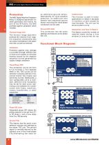
MIG M Family Digital Machine Protection Relay Protection The MIG Digital Machine Protection Relay is designed specifically for small generators and motors. As part of the M Family, the MIG provides superior protection which includes: Thermal Image Unit The thermal image algorithm protects the machine from negative sequence components that can cause overheating in the stator and rotor, as well as overload. an additional ground sensor. Alternatively, for more sensitive detection, an additional core balance (zero sequence) ground sensor encircling the three-phase conductors can be used. Starts/Hour...
Open the catalog to page 2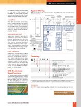
MIG M Family Digital Machine Protection Relay Typical Wiring Note: Only for reference. For particular connections for any MIG model, please refer to its external connections drawing. ZERO SEQUENCE GROUND SENSING CONNECTION Locked Rotor The MIG provides protection during extra-long start-ups where excessive overcurrent conditions can damage rotors. This protection is critical for power applications where the motor drives the generator into service. 20 A MAX CIRCUIT BREAKER LOCATED BEFORE POWER INPUT ZERO SEQUENCE GROUND CT CAUTION: Fork or ring terminals must be used on the termainal block. NOTE:...
Open the catalog to page 3All GE Grid Solutions catalogs and technical brochures
 Static Var Compensator Solutions
12 Pages
 Kelman TRANSFIX
2 Pages
 Kelman MINITRANS
2 Pages
 DTR
DTR4 Pages
 SPM
SPM8 Pages
 TOV
TOV3 Pages
 MDS SD Series
4 Pages
 MIC
MIC2 Pages
 Multilin F60
9 Pages
 Model PT7-1-150 & PT7-1-200
2 Pages
 Models PT7-2-150 & PT7-2-200
2 Pages
 Model PT6-2-125
2 Pages
 Model PT6-1-125
2 Pages
 Models PTW5-1-110&PTW5-2-110
2 Pages
 Models PTG4-1-75 & PTG4-2-75
2 Pages
 Models PTW3-1-60 & PTW3-2-60
2 Pages
 Models PTG3-1-60 & PTG3-2-60
2 Pages
 Models PT3-1-45 & PT3-2-45
2 Pages
 Model 3PT3-60
2 Pages
 MIG II
8 Pages
 Model JVW-110C
2 Pages
 Model JVW-5AC-1
2 Pages
 Model JVW-5C
2 Pages
 Multilin T60
9 Pages
 Multilin 489
9 Pages
 Multilin™ D25
8 Pages
 Multilin D485
1 Page
 Multilin P485
1 Page
 MultiNet
3 Pages
 iNET-II
4 Pages
 MDS™ iNET 300
2 Pages
 MDS iNET 900®
2 Pages
 Multilin™ PQM II
8 Pages
 Multilin L90
10 Pages
 COSI
COSI2 Pages
 Reason DR60
4 Pages
 Multilin 850
4 Pages
 G650
G6508 Pages
 Hydran M2
2 Pages
 MultiLink ML3000 Series
12 Pages
 TN1U
TN1U4 Pages
 JungleMUX SONET Multiplexer
4 Pages
 Multilin™ MM200
8 Pages
 Multilin™ MM300
8 Pages
 Multilin 339
16 Pages
 Multilin 469
10 Pages
 Multilin A60
6 Pages
 Multilin 350
16 Pages
 Multilin F650
12 Pages
 Multilin 750/760
10 Pages
 F35
F358 Pages
 345
34512 Pages
 745
7458 Pages
 Multilin G30
9 Pages
 Transmission Overview
9 Pages
 Air-Core Reactors
8 Pages
 Multilin HardFiber System
14 Pages
 Multilin UR & URPlus
18 Pages
 Multilin C30
6 Pages
 Voltage Regulators
16 Pages
 g3 Technology
2 Pages
 Rectifier
4 Pages
 RMIO
RMIO2 Pages
 MiCOM Agile P54A/B
2 Pages
 MultiSync™ 100
6 Pages
 Multilin G60
9 Pages
 Multilin D400
12 Pages
 GL 107X
2 Pages
 Disconnectors
12 Pages
 CGVB-05
2 Pages
 KOTEF
KOTEF4 Pages
 Adjustable Height Sub Base
2 Pages
 HV Transmission Solutions
8 Pages
 FK
FK4 Pages
 B65
B654 Pages
 Safe-NET Network Transformer
8 Pages
 Green Power Transformers
4 Pages
 COSI-RogoFlex
2 Pages
 Grid-GA-L3-COSI_CEVT
2 Pages
 P50 Agile P154 / P253
4 Pages
 MiCOM Agile P24x
8 Pages
 239 Motor Protection
8 Pages
 Power Transformers
8 Pages
 smorb
smorb3 Pages
 MIF II
8 Pages
 SR family
2 Pages
 735/737
4 Pages
 hid
hid2 Pages
 dtp
dtp5 Pages
 IEC Oil Filled & SF
12 Pages
 Gas Insulated Switchgear
24 Pages
 Multilin UR & UR Plus
18 Pages
 M60
M608 Pages
 MDS Orbit Platform Brochure
12 Pages





Archived catalogs


- GE Vernova dry transformer
- Digital I/O
- IO module
- Analog I/O
- Digital IO module
- Capacitor
- Isolator switch
- Current transformer
- IEC transformer
- Signal amplifying integrated circuit
- Encapsulated transformer
- Power transformer
- Single-phase transformer
- Analog IO module
- Industrial communication router
- GE Vernova industrial transformer
- Serial I/O