


MIF II

MIF II
The MIF II is a protection relay designed for primary circuit protection in distribution networks and as backup protection for transformers, generators, and motors. It features advanced digital protection capabilities, including time-delayed overcurrent, instantaneous overcurrent, and thermal image protection. The relay offers flexible settings and selectable models for precise coordination with other devices.
The MIF II provides phase and ground time overcurrent (TOC) and instantaneous overcurrent (IOC) protection. It includes thermal image protection and supports various time-current curves such as IAC and EPTAR-C. Additional features include circuit breaker control, autorecloser functionality, and configurable breaker failure to open. It has six outputs for trip, service required, and auxiliary functions.
The relay includes a 32-event record, analog/digital oscillography, and a KI2 counter for breaker maintenance. It offers per-phase current metering and displays information on the last five trips.
The MIF II features EnerVista™ software for setting and monitoring, a 2x16 character LCD display, and six LED indicators with configurable functions and colors. It supports multiple protocols, including ModBus RTU and IEC 60870-5-103.
The EnerVista™ suite simplifies working with Multilin devices, providing tools for monitoring, maintenance, and integration into DCS or SCADA systems. It includes COMTRADE and Sequence of Events viewers for event analysis.
The MIF II offers low-priced scalable options, reduces troubleshooting and maintenance costs, and provides design flexibility with easy-to-use programming logic. It supports asset monitoring, configurable logic, curves, I/Os, and LEDs, and includes flash memory for field upgrades.
The relay is suitable for primary feeder protection on distribution networks and backup/auxiliary protection for transformers, generators, and motors.
The MIF II provides economical feeder protection with recloser, reduces maintenance costs, and offers improved user interface and access to information via Modbus RTU communications.
The basic unit includes two inputs and six outputs, with options for user configuration. It supports multiple setting groups and metering for phase and ground currents.
Includes event recording, oscillography, and configurable I/O and LEDs.
Includes cold load pickup, breaker failure protection, and breaker health monitoring.
The relay features a front RS232 and a rear RS485 port, supporting ModBus RTU protocol. It is compatible with MultiNet™ for Ethernet connectivity.
Detailed dimensions are provided for installation purposes.
The MIF II Feeder Protection System offers comprehensive protection and control features, advanced monitoring and metering capabilities, and user-friendly interfaces, making it a versatile solution for various protection applications.
EnerVista™ Launchpad is a comprehensive software package designed for configuring and maintaining Multilin products. It allows real-time device configuration via serial, Ethernet, or modem connections, and offline configuration by creating setting files. The package includes a document management system ensuring access to up-to-date manuals, application notes, specifications, brochures, wiring diagrams, FAQs, and service bulletins.
Viewpoint Monitoring is a user-friendly software for monitoring and data recording in small systems. It offers a complete HMI package with features like plug-and-play device monitoring, system single-line monitoring and control, annunciator alarm screens, trending reports, and automatic event and waveform retrieval.
The MIF II Feeder Protection System includes various inputs and outputs for protection and control. Key inputs include disabling functions for phase and ground protection, while outputs manage phase trips, ground trips, and alarms. The system supports both AC and DC power inputs and is equipped with a range of communication options, including ModBus® RTU and IEC 60870-5-103 protocols.
- Environmental: Operates between -20ºC to +60ºC with up to 95% humidity without condensing.
- Protection: Features phase/ground time overcurrent and instantaneous overcurrent protection with precise pickup and dropout levels.
- Communications: Includes local and remote communication capabilities with a 2x16 LCD display and a frontal keypad.
- Metering: Provides fundamental current accuracy of ±1% at rated current.
- Monitoring: Offers oscillography and event recording with a capacity of 32 events.
- Inputs and Outputs: Supports various AC current inputs and digital inputs with specific voltage levels.
- Power Supply: Available in low and high range DC and AC voltage options.
The system conforms to various international standards for insulation, surge, electrostatic discharge, radio interference, and more. It is certified under CNL and UL standards and manufactured to ISO9001 standards.
The interface includes a 16x2 character LCD display, RS232 communications port, programmable status LEDs, and control keys for settings access without a computer.
Catalog excerpts

FEEDER PROTECTION SYSTEM Economical feeder protection with recloser KEY BENEFITS • Low priced scalable options – event reports, waveform capture, reclosure • Reduce troubleshooting and maintenance cost – Event reports, waveform capture • Automatic display of last fault information • Design flexibility – Easy to use programming logic • Asset monitoring – Breaker health, and breaker failure • Access to information – Modbus RTU communications • Configurable logic, curves, I/Os and LEDs • Flash memory for field upgrades • Password protection for local operation • AC/DC power supply • Improved user interface • Access via front panel keypad or communication links • EnerVista™ compatible • Isolated front RS232 serial port APPLICATIONS • Primary feeder protection on distribution networks • Backup/auxiliary protection for transformers, generators and motors FEATURES Protection and Control User Interfaces • EnerVista™ for setting and monitoring • Thermal image protection • 6 LED indicators, 4 configurable in function and colour. • EPTAR-C time-current curves • Independent front RS232 and rear RS485 • Circuit breaker control (open and close) • Multiple Protocols - ModBus RTU, IEC 60870-5-103 • Four shot autorecloser • Cold load pickup element EnerVista™ Software • Configurable breaker failure to open • EnerVista™ software - an industry leading suite of software tools that simplifies every aspect of working with Multilin devices • Configurable I/O • 6 outputs: trip, service required, 4 auxiliary Monitoring & Metering • 32-event record • Analog/digital oscillography • KI2 counter for breaker maintenance • Per phase current metering • Monitoring of the last 5 trips information from the display • EnerVista™ Integrator providing easy integration of data in the MIFII into new or existing monitoring and control systems
Open the catalog to page 1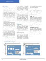
Overview The MIF II is a member of the M II Family of protection relays. This relay is used to perform primary circuit protection on distribution networks at any voltage level, and backup/auxiliary protection for transformers, generators and motors. Basic protection features include time delayed overcurrent , instantaneous overcurrent (two levels), and thermal image protection. Overcurrent elements can be three-phase and ground or single phase, depending on the selected model. An optional protection offering is also provided for cold load pickup, breaker failure protection, breaker health, configurable...
Open the catalog to page 2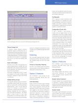
events, and includes the values of currents and status of all the protection elements at the moment of the event. Oscillography MIF II captures current waveforms and digital channels at 8 samples per cycle. One oscillography record with a maximum length of 24 cycles is stored in memory. Oscillography is triggered either by internal signals or an external contact. Use the oscillography feature as an accurate troubleshooting and diagnostics tool Thermal Image Unit A thermal image element protects equipment against overheating due to excessive load. Several operating curves can be set as a function...
Open the catalog to page 3
Configurable Logic Up to a maximum of 4 configurable logic schemes can be implemented into the MIF II by means of using a set of 4 pre-configured logic gates and timer cells. A graphical user interface is provided for configuration of MIF II logic. The inputs of the MIF II configurable logic can be assigned to contact outputs and/or LEDs. Circuit Breaker Control The MIF II permits operation of the circuit breaker. Breaker opening and closing operations can be carried out by programming specific outputs, and digital inputs can be used for verifying the success of the operation. Autorecloser The...
Open the catalog to page 4
Communication Ports A front mounted RS232 and a rear RS485 port allow easy user interface via a PC. ModBus® RTU protocol is used for all ports. The relay supports baud rates from 300 to 19,200 bps. Up to 32 Multilin devices can be addressed on a single communications channel. A unique address must be assigned to each relay via a setting when multiple relays are connected. MultiNet™ compatible MultiNetTM is a communications module that provides Multilin serial ModBus IEDs with ModBus TCP/IP communications over Ethernet, allowing connection to fiber optic LAN and WAN network systems. MultiNet TM...
Open the catalog to page 5
Typical Wiring CAUTION: FORK OR RING TERMINALS MUST BE USED ON THE TERMINAL BLOCK NOTES: SUITABLE DISCONNECT DEVICES RECOMMENDED LOCATED NEAR THE RELAY ALTERNATIVE CT WIRING FOR RESIDUAL GROUND SENSING OVERVOLTAGE CATEGORY: II ZERO SEQUENCE GROUND SENSING CONNECTION ZERO SEQUENCE GROUND CT 20 A MAX CIRCUIT BREAKER LOCATED BEFORE POWER INPUT NOTE: 14 AWG wiring recommended SAFETY GND GROUND GROUND BUS PROGRAMMABLE CONTROLLER (*) Terminals B12, A12 and B11 must be connected to SELV (safety extra-low voltage) parts (on the PLC). They are not to be tested for hipot test under any circumstance (**)...
Open the catalog to page 6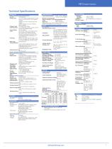
Technical Specifications PROTECTION PHASE / GROUND TIME OVERCURRENT Current: Fundamental Pickup Level: 0.1 – 2.4 times In (rated current) in steps of 0.01 x In (51P & 51G if 1/5 A ground models). 0.005-0.12 A (51G in sensitive ground model) 0.002-0.048 A (51G in very sensitive ground model) Dropout Level: 97% (typical) of Pickup Level Accuracy: ±1% of injected current at rated current ±3% in the complete range Curve Shapes: IEC (B.S.) A/B/C Level: ±1% at the rated current ANSI Inverse, Very Inverse or Extremely Inverse IAC Inverse, Very Inverse, Extremely Inverse, Inverse Short or Inverse Long...
Open the catalog to page 7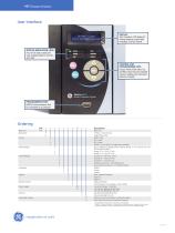
User Interface DISPLAY 16x2 characters LCD display for viewing setpoints, actual value messages, and fault reports STATUS INDICATION LEDs Four of six status LEDs are user programmable in function and color CONTROL AND PROGRAMMING KEYS Escape, Reset, Enter, Menu Up, and Menu Down keys for complete access to settings and information without a computer PROGRAMMING PORT RS232 Communications Port for connection to a computer Ordering MIF Base Unit Application Curves Base Unit 3 Phase + Ground relay Single Phase relay ANSI Curves IEC Curves IAC Curves EPTAR-C curves (only for single phase models) No...
Open the catalog to page 8All GE Grid Solutions catalogs and technical brochures
 Static Var Compensator Solutions
12 Pages
 Kelman TRANSFIX
2 Pages
 Kelman MINITRANS
2 Pages
 MIG
MIG3 Pages
 DTR
DTR4 Pages
 SPM
SPM8 Pages
 TOV
TOV3 Pages
 MDS SD Series
4 Pages
 MIC
MIC2 Pages
 Multilin F60
9 Pages
 Model PT7-1-150 & PT7-1-200
2 Pages
 Models PT7-2-150 & PT7-2-200
2 Pages
 Model PT6-2-125
2 Pages
 Model PT6-1-125
2 Pages
 Models PTW5-1-110&PTW5-2-110
2 Pages
 Models PTG4-1-75 & PTG4-2-75
2 Pages
 Models PTW3-1-60 & PTW3-2-60
2 Pages
 Models PTG3-1-60 & PTG3-2-60
2 Pages
 Models PT3-1-45 & PT3-2-45
2 Pages
 Model 3PT3-60
2 Pages
 MIG II
8 Pages
 Model JVW-110C
2 Pages
 Model JVW-5AC-1
2 Pages
 Model JVW-5C
2 Pages
 Multilin T60
9 Pages
 Multilin 489
9 Pages
 Multilin™ D25
8 Pages
 Multilin D485
1 Page
 Multilin P485
1 Page
 MultiNet
3 Pages
 iNET-II
4 Pages
 MDS™ iNET 300
2 Pages
 MDS iNET 900®
2 Pages
 Multilin™ PQM II
8 Pages
 Multilin L90
10 Pages
 COSI
COSI2 Pages
 Reason DR60
4 Pages
 Multilin 850
4 Pages
 G650
G6508 Pages
 Hydran M2
2 Pages
 MultiLink ML3000 Series
12 Pages
 TN1U
TN1U4 Pages
 JungleMUX SONET Multiplexer
4 Pages
 Multilin™ MM200
8 Pages
 Multilin™ MM300
8 Pages
 Multilin 339
16 Pages
 Multilin 469
10 Pages
 Multilin A60
6 Pages
 Multilin 350
16 Pages
 Multilin F650
12 Pages
 Multilin 750/760
10 Pages
 F35
F358 Pages
 345
34512 Pages
 745
7458 Pages
 Multilin G30
9 Pages
 Transmission Overview
9 Pages
 Air-Core Reactors
8 Pages
 Multilin HardFiber System
14 Pages
 Multilin UR & URPlus
18 Pages
 Multilin C30
6 Pages
 Voltage Regulators
16 Pages
 g3 Technology
2 Pages
 Rectifier
4 Pages
 RMIO
RMIO2 Pages
 MiCOM Agile P54A/B
2 Pages
 MultiSync™ 100
6 Pages
 Multilin G60
9 Pages
 Multilin D400
12 Pages
 GL 107X
2 Pages
 Disconnectors
12 Pages
 CGVB-05
2 Pages
 KOTEF
KOTEF4 Pages
 Adjustable Height Sub Base
2 Pages
 HV Transmission Solutions
8 Pages
 FK
FK4 Pages
 B65
B654 Pages
 Safe-NET Network Transformer
8 Pages
 Green Power Transformers
4 Pages
 COSI-RogoFlex
2 Pages
 Grid-GA-L3-COSI_CEVT
2 Pages
 P50 Agile P154 / P253
4 Pages
 MiCOM Agile P24x
8 Pages
 239 Motor Protection
8 Pages
 Power Transformers
8 Pages
 smorb
smorb3 Pages
 SR family
2 Pages
 735/737
4 Pages
 hid
hid2 Pages
 dtp
dtp5 Pages
 IEC Oil Filled & SF
12 Pages
 Gas Insulated Switchgear
24 Pages
 Multilin UR & UR Plus
18 Pages
 M60
M608 Pages
 MDS Orbit Platform Brochure
12 Pages





Archived catalogs


- GE Vernova dry transformer
- Digital I/O
- IO module
- Analog I/O
- Digital IO module
- Capacitor
- Isolator switch
- Current transformer
- IEC transformer
- Signal amplifying integrated circuit
- Encapsulated transformer
- Power transformer
- Single-phase transformer
- Analog IO module
- Industrial communication router
- GE Vernova industrial transformer
- Serial I/O