745
1 /8Pages

745
1 /8Pages
Catalog excerpts

Transformer Protection 745 Transformer Protection System High-speed, draw-out transformer protection and management • Easy to use Transformer Protection System supported by industry leading suite of software tools to optimize transformer performance and to extend life expectancy • Improved security for transformer energization using superior Adaptive 2nd Harmonic Restraint algorithm • Accurate built-in metering functions - Eliminates auxiliary metering devices and reduces cost • Advanced automation capabilities using FlexLogic to provide customized protection and control solutions • Fast, flexible and reliable communications - Embedded 10BaseT Ethernet capability provides faster data transfer for improved system performance • Minimize replacement time - Draw-out construction ideal in industrial environments • Reduce troubleshooting time and maintenance costs - IRIG-B time synchronization, event reports, waveform capture, data logger • Simplified testing - Built in simulation features for setpoint verification including waveform playback for relay setting verification • Cost effective access to information - Modbus and DNP 3.0 Level 2 protocols through embedded Ethernet, standard RS232, RS485 & RS422 serial ports. • Globally accepted - Member of the most renowned product family in the market. • Extended life - Optional conformal coating for chemically corrosive and humid environments • Fast and easy troubleshooting, improved maintenance procedures and increased device security - Security Audit Trail provides detailed traceability for system configuration changes Applications • Primary and back-up protection and management of small, medium and larger power transformers, autotransformers and reactors • Transformer asset monitoring using Hottest Spot, Loss-ofLife and Aging Factor • Stand-alone or component in automated substation control system Features Protection and Control • Variable dual-slope percent differential protection • Metering - current, voltage, sequence components per winding, power, energy, voltage • THD and harmonics up to the 21st • Event recording - 128 time tagged events • Tap position up to 50 tap positions • Ambient temperature /analog transducer input Magnetizing inrush and overexcitation blocking Phase & ground overcurrent elements Adaptive time overcurrent using FlexCurves elements Underfrequency/Overfrequency Protection • Frequency rate-of-change Detection • Overexcitation (V/Hz) Protection • Restricted Ground Fault Protection • Transformer overload protection Communications • Networking interfaces - 10Mbps Ethernet, RS232, RS485 and RS422 ports • Ethernet port, 10Mbps • Multiple protocols - ModBus™ RTU, ModBus™ RTU TCP/IP, DNP 3.0 Level 2 Digital Energy Multilin • Analog transducer input • Oscillography & Data Logger - 10 records up to 32 power cycles • Simulation mode and playback capability. EnerVista™ Software • Sophisticated software for configuration and commissioning • Graphical Logic Designer and Logic Monitor to simplify designing and testing procedures • Document and software archiving toolset • EnerVista™ Integrator providing easy inte
Open the catalog to page 1
745 Transformer Protection System signal for better through fault stability under CT saturation conditions. The 745 offers great performance in dealing with magnetizing current inrush, by providing three program able restraint m methods, each of which can be enabled or disabled by the user. An increase in transformer voltage or decrease in system frequency may result in overexcitation of the transformer. It is often desirable to prevent operation of the percent differential element in these cases therefore a fifth harmonic inhibit is integrated into the percent differential element to cater for...
Open the catalog to page 2
745 Transformer Protection System Multiple Settings Groups For Delta/Wye impedance grounded transformers, overcurrent protection is particularly difficult to set . A negative sequence based overcurrent element provides the required sensitivity phase faults. Each winding is given its own element with the same programmable characteristics as the phase and neutral TOC elements. This feature provides an estimate of how much of the transformer’s total insulation life has elapsed (based on IEEE Standards C57.91-1995, “IEEE Guide for Loading Mineral-Oil-Immersed Transformers,” and C57.96-1989, “IEEE...
Open the catalog to page 3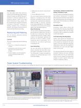
745 Transformer Protection System Output Relays Transformer Protection One high-speed solid state electronic output can be activated by any protection element through user-defined FlexLogic™ equa ions or directly assigned from a t protection element. Seven of the eight electro-mechanical relay outputs can be activated by the protection elements according to FlexLogic™ equations or directly assigned from a protection element. One output is factory set as an internal self-test failure alarm relay. Monitoring and Metering The 745 features advanced metering functions including: Currents The 745 accurately...
Open the catalog to page 4
745 Transformer Protection System The 745 offers additional features designed for ease of use: Auto CT Configuration All CTs are connected in a wye configuration for simplicity. All phase and magnitude corrections as well as zero-sequence current compensation are performed automatically based on a choice of over 100 transformer types. Dynamic CT Ratio Mismatch Correction Variances in on-load tap position output are monitored and corrected. In addition, external compensation CT’s are not required. Field Upgradable Option An optional pass-code key may be purchased to allow field upgrades. Field...
Open the catalog to page 5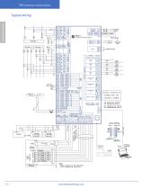
745 Transformer Protection System Transformer Protection Typical Wiring Multilin 745 Transformer Protection System
Open the catalog to page 6
745 Transformer Protection System Technical Specifications protection Signal source: Winding 1 Phase A current/ voltage Level accuracy: ±0.02 Hz Operate time (delay set to 0.0 sec): Solid state output: @3% beyond pickup: 120–150ms Relay outputs 2 – 5: @ 3% beyond pickup: 125–155ms OVEREXCITATION on 5th harmonic level Definite time element: Operating current pickup: 0.03 – 1.00 in steps of 0.01x CT 0.1 – 99.9 in steps of 0.1% Pickup level: Dropout: 95% of pickup Time delay: 0 – 60,000 sec in steps of 1 sec Signal source: All phase currents Operate time (delay set to 0.0 sec): Solid state output:...
Open the catalog to page 7All GE Grid Solutions catalogs and technical brochures
 Static Var Compensator Solutions
12 Pages
 Kelman TRANSFIX
2 Pages
 Kelman MINITRANS
2 Pages
 MIG
MIG3 Pages
 DTR
DTR4 Pages
 SPM
SPM8 Pages
 TOV
TOV3 Pages
 MDS SD Series
4 Pages
 MIC
MIC2 Pages
 Multilin F60
9 Pages
 Model PT7-1-150 & PT7-1-200
2 Pages
 Models PT7-2-150 & PT7-2-200
2 Pages
 Model PT6-2-125
2 Pages
 Model PT6-1-125
2 Pages
 Models PTW5-1-110&PTW5-2-110
2 Pages
 Models PTG4-1-75 & PTG4-2-75
2 Pages
 Models PTW3-1-60 & PTW3-2-60
2 Pages
 Models PTG3-1-60 & PTG3-2-60
2 Pages
 Models PT3-1-45 & PT3-2-45
2 Pages
 Model 3PT3-60
2 Pages
 MIG II
8 Pages
 Model JVW-110C
2 Pages
 Model JVW-5AC-1
2 Pages
 Model JVW-5C
2 Pages
 Multilin T60
9 Pages
 Multilin 489
9 Pages
 Multilin™ D25
8 Pages
 Multilin D485
1 Page
 Multilin P485
1 Page
 MultiNet
3 Pages
 iNET-II
4 Pages
 MDS™ iNET 300
2 Pages
 MDS iNET 900®
2 Pages
 Multilin™ PQM II
8 Pages
 Multilin L90
10 Pages
 COSI
COSI2 Pages
 Reason DR60
4 Pages
 Multilin 850
4 Pages
 G650
G6508 Pages
 Hydran M2
2 Pages
 MultiLink ML3000 Series
12 Pages
 TN1U
TN1U4 Pages
 JungleMUX SONET Multiplexer
4 Pages
 Multilin™ MM200
8 Pages
 Multilin™ MM300
8 Pages
 Multilin 339
16 Pages
 Multilin 469
10 Pages
 Multilin A60
6 Pages
 Multilin 350
16 Pages
 Multilin F650
12 Pages
 Multilin 750/760
10 Pages
 F35
F358 Pages
 345
34512 Pages
 Multilin G30
9 Pages
 Transmission Overview
9 Pages
 Air-Core Reactors
8 Pages
 Multilin HardFiber System
14 Pages
 Multilin UR & URPlus
18 Pages
 Multilin C30
6 Pages
 Voltage Regulators
16 Pages
 g3 Technology
2 Pages
 Rectifier
4 Pages
 RMIO
RMIO2 Pages
 MiCOM Agile P54A/B
2 Pages
 MultiSync™ 100
6 Pages
 Multilin G60
9 Pages
 Multilin D400
12 Pages
 GL 107X
2 Pages
 Disconnectors
12 Pages
 CGVB-05
2 Pages
 KOTEF
KOTEF4 Pages
 Adjustable Height Sub Base
2 Pages
 HV Transmission Solutions
8 Pages
 FK
FK4 Pages
 B65
B654 Pages
 Safe-NET Network Transformer
8 Pages
 Green Power Transformers
4 Pages
 COSI-RogoFlex
2 Pages
 Grid-GA-L3-COSI_CEVT
2 Pages
 P50 Agile P154 / P253
4 Pages
 MiCOM Agile P24x
8 Pages
 239 Motor Protection
8 Pages
 Power Transformers
8 Pages
 smorb
smorb3 Pages
 MIF II
8 Pages
 SR family
2 Pages
 735/737
4 Pages
 hid
hid2 Pages
 dtp
dtp5 Pages
 IEC Oil Filled & SF
12 Pages
 Gas Insulated Switchgear
24 Pages
 Multilin UR & UR Plus
18 Pages
 M60
M608 Pages
 MDS Orbit Platform Brochure
12 Pages


Archived catalogs


- GE Vernova dry transformer
- Digital I/O
- IO module
- Analog I/O
- Capacitor
- Digital IO module
- Circuit breaker
- Protection relay
- Current transformer
- Isolator switch
- Signal amplifying integrated circuit
- IEC transformer
- Encapsulated transformer
- Single-phase transformer
- Industrial communication router
- Analog IO module
- GE Vernova industrial transformer
- Serial I/O