- Catalogs
- GE Grid Solutions
- 239 Motor Protection
239 Motor Protection
1 /8Pages

239 Motor Protection
1 /8Pages
Catalog excerpts

MOTOR PROTECTION SYSTEM Motor protection and management for small to medium size motors Enhanced Motor Overload Protection with Thermal Modeling Simple configuration and system monitoring using EnerVista™ 239 Setup software Reduced cost and commissioning time with Protection, Monitoring, and Control in a single device Scalable protection with optional RTD inputs and advanced Motor Protection elements • Simplified testing and commissioning with built in simulation features • Field upgradable firmware and relay options • Easy access to system and relay information using Modbus RTU Motor Protection APPLICATIONS • Multiple groups of protection settings allows flexible protection for flexible systems FEATURES • Small to Medium sized three phase AC induction and synchronous motors • Pumps, conveyors, compressors, fans, etc. Protection and Control • Thermal Overload (15 selectable curves) - Trip and alarm, immediate current overload alarm • Phase short circuit • Mechanical jam • Thermal memory lockout • Single-Phasing /Current unbalance • Ground fault - trip and alarm • Overtemperature: via thermistor or optional RTD inputs • Undercurrent • Breaker Failure • Trip/alarm/auxiliary/service outputs • Multi-speed motor protection • Motor start supervision Communications • RS485 Serial Communications • Modbus RTU protocol Monitoring and Metering • Status/current/temperature display • Fault diagnosis • Trending • Trip record, last 5 • Process control • Optional analog output User Interface • 40 Character backlit display for easy viewing of settings and actual values • 6 Motor and relay status LED's • Multiple programming keys to allow easy access to system values and relay settings EnerVista™ Software • State of the art software for configuration and commissioning GE Multilin products • Document and software archiving toolset to ensure reference material and device utilities are up-to-date • EnerVista™ Integrator providing easy integration of data in the 239 into new or existing monitoring and control systems
Open the catalog to page 1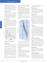
239 Motor Protection System The 239 is a digital motor protection system designed for three phase AC motors and associated mechanical equipment . Advanced protection features include: Thermal Overload This function calculates the thermal capacity used by the motor during different stages of the motor operation. The value is updated based on the timecurrent overload characteristics and the motor overload lockout time setpoints. Motor Starting Motor Protection During acceleration, the motor is protected by an I2t overcurrent curve which passes through the setpoints “Locked Rotor Current” and cold...
Open the catalog to page 2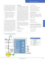
239 Motor Protection System dust. The 239 can trigger a trip or an alarm if the ground pickup level is exceeded. A time delay may be entered for time coordination of systems with several levels of ground fault detection. There are two ground inputs available in the 239, allowing two methods of ground protection. • Core balance (Zero sequence) High Impedance Ground Fault (HGF) current transformers with 5A secondary • Core balance (Zero sequence) current transformers with a 50:0.025 Amp current ratio for sensitive current detection. When the residual connection of the phase CTs is used to detect...
Open the catalog to page 3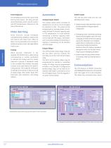
239 Motor Protection System Fault Diagnosis The 239 keeps a record of the cause of the last five trips issued. The relay will also record the phase current, ground current, and RTD temperatures measured at the time of the last trip. Motor Alarming Alarm functions include immediate overload warning, unbalance, undercurrent and internal self check fault . Often an alarm can be generated soon enough to enable corrective action to be taken before a trip occurs. Testing Motor Protection While periodic calibration is not required, the PICKUP LED is useful during commissioning or routine verification...
Open the catalog to page 4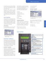
239 Motor Protection System and setpoints to be remotely accessed by a PLC or SCADA system. A front panel LED verifies correct operation of the communication port. The 239 is also capable of being integrated into a local area network using the Multinet™ Serial to Ethernet converter. Networking allows easy access to information from multiple monitoring and control devices such as SCADA's and HMI's. User Interface The 40 character LCD and keypad provide convenient local communications and control. Setpoints can be modified locally using the keypad and display. To help prevent unauthorized setpoint...
Open the catalog to page 5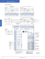
Typical Wiring -------------RESIDUAL GROUND CONNECTION -PHASE A CT ZERO SEQUENCE GROUND CONNECTION ------- Motor Protection STATOR THERMISTOR EMERGENCY RESTART EXTERNAL RESET 1) RELAY CONTACT STATE SHOWN WITH CONTROL POWER NOT APPLIED. 2) RELAY FACTORY DEFAULTS: TRIP, ALARM, AUXILIARY: NON-FAILSAFE SERVICE: FAILSAFE SHIELD TERMINALS ARE INTERNALLY CONNECTED TO SAFETY GROUND TERMINAL 13 4) RTD TEMPERATURE SENSING AND ANALOG OUTPUT OPTIONAL
Open the catalog to page 6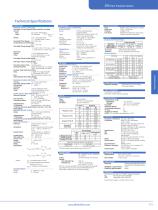
239 Motor Protection System Technical Specifications PROTECTION PROTECTION thermal model / overload overload Curves: separate start and Run Overload Curves Run: 15 Curves, fixed shape start: Per Equation: T(I) = Tsst x I2 I2LRC Where: Tsst = Save Stall Time ILRC = Locked Rotor Current save stall Time Range: 1.0 - 600.0 sec Locked Rotor Current Range: 0.5 - 11.0 x FLC Overload Pickup Range (FLC): 0.1-150 A for CT Pri Set < 50A 1-1500 A for CT Pri Set > 50 A THERMAL MODEL / RTDs (OPTION) Inputs: Type: Range: Trip/alarm range: Dead band: Accuracy: Lead Resistance: 3 RTDs, stator/bearing...
Open the catalog to page 7
239 Motor Protection System H Harsh enviornment conformal coating Motor Protection Modifications MOD500: Portable test/carrying case MOD504: Removable terminal blocks MOD505: Enhanced start protection MOD506: Custom programmable overload curve MOD509: Directional ground sensing with 120 V AC polarizing voltage MOD513: Class 1 Division 2 operation MOD517: Australian Mines approval • Multinet Serial to Ethernet converter MULTINET-FE Visit www.GEMultilin.com/239 to:- • View Guideform Specifications • Download the instruction manual • Review applications notes and support...
Open the catalog to page 8All GE Grid Solutions catalogs and technical brochures
 Static Var Compensator Solutions
12 Pages
 Kelman TRANSFIX
2 Pages
 Kelman MINITRANS
2 Pages
 MIG
MIG3 Pages
 DTR
DTR4 Pages
 SPM
SPM8 Pages
 TOV
TOV3 Pages
 MDS SD Series
4 Pages
 MIC
MIC2 Pages
 Multilin F60
9 Pages
 Model PT7-1-150 & PT7-1-200
2 Pages
 Models PT7-2-150 & PT7-2-200
2 Pages
 Model PT6-2-125
2 Pages
 Model PT6-1-125
2 Pages
 Models PTW5-1-110&PTW5-2-110
2 Pages
 Models PTG4-1-75 & PTG4-2-75
2 Pages
 Models PTW3-1-60 & PTW3-2-60
2 Pages
 Models PTG3-1-60 & PTG3-2-60
2 Pages
 Models PT3-1-45 & PT3-2-45
2 Pages
 Model 3PT3-60
2 Pages
 MIG II
8 Pages
 Model JVW-110C
2 Pages
 Model JVW-5AC-1
2 Pages
 Model JVW-5C
2 Pages
 Multilin T60
9 Pages
 Multilin 489
9 Pages
 Multilin™ D25
8 Pages
 Multilin D485
1 Page
 Multilin P485
1 Page
 MultiNet
3 Pages
 iNET-II
4 Pages
 MDS™ iNET 300
2 Pages
 MDS iNET 900®
2 Pages
 Multilin™ PQM II
8 Pages
 Multilin L90
10 Pages
 COSI
COSI2 Pages
 Reason DR60
4 Pages
 Multilin 850
4 Pages
 G650
G6508 Pages
 Hydran M2
2 Pages
 MultiLink ML3000 Series
12 Pages
 TN1U
TN1U4 Pages
 JungleMUX SONET Multiplexer
4 Pages
 Multilin™ MM200
8 Pages
 Multilin™ MM300
8 Pages
 Multilin 339
16 Pages
 Multilin 469
10 Pages
 Multilin A60
6 Pages
 Multilin 350
16 Pages
 Multilin F650
12 Pages
 Multilin 750/760
10 Pages
 F35
F358 Pages
 345
34512 Pages
 745
7458 Pages
 Multilin G30
9 Pages
 Transmission Overview
9 Pages
 Air-Core Reactors
8 Pages
 Multilin HardFiber System
14 Pages
 Multilin UR & URPlus
18 Pages
 Multilin C30
6 Pages
 Voltage Regulators
16 Pages
 g3 Technology
2 Pages
 Rectifier
4 Pages
 RMIO
RMIO2 Pages
 MiCOM Agile P54A/B
2 Pages
 MultiSync™ 100
6 Pages
 Multilin G60
9 Pages
 Multilin D400
12 Pages
 GL 107X
2 Pages
 Disconnectors
12 Pages
 CGVB-05
2 Pages
 KOTEF
KOTEF4 Pages
 Adjustable Height Sub Base
2 Pages
 HV Transmission Solutions
8 Pages
 FK
FK4 Pages
 B65
B654 Pages
 Safe-NET Network Transformer
8 Pages
 Green Power Transformers
4 Pages
 COSI-RogoFlex
2 Pages
 Grid-GA-L3-COSI_CEVT
2 Pages
 P50 Agile P154 / P253
4 Pages
 MiCOM Agile P24x
8 Pages
 Power Transformers
8 Pages
 smorb
smorb3 Pages
 MIF II
8 Pages
 SR family
2 Pages
 735/737
4 Pages
 hid
hid2 Pages
 dtp
dtp5 Pages
 IEC Oil Filled & SF
12 Pages
 Gas Insulated Switchgear
24 Pages
 Multilin UR & UR Plus
18 Pages
 M60
M608 Pages
 MDS Orbit Platform Brochure
12 Pages


Archived catalogs


- GE Vernova dry transformer
- Digital I/O
- IO module
- Analog I/O
- Digital IO module
- Capacitor
- Circuit breaker
- Protection relay
- Isolator switch
- Signal amplifying integrated circuit
- IEC transformer
- Encapsulated transformer
- Power transformer
- Single-phase transformer
- Industrial communication router
- Analog IO module
- GE Vernova industrial transformer
- Serial I/O