- Catalogs
- GE Gas Turbines
- GE10-2 15 ppm combustor
GE10-2 15 ppm combustor
1 /3Pages

GE10-2 15 ppm combustor
1 /3Pages
Catalog excerpts

One of the critical factors in gas turbine design today is emissions reduction. In mature markets such as the USA, permits to install new gas turbines include increasingly restrictive emissions requirements across a wide range of ambient temperatures and loads. To meet these requirements, GE Energy has developed a new combustor for the latest version of its heavy duty GE 10-2 gas turbine, a 12 MW class, double shaft machine used predominantly for mechanical drive applications but also available for power generation. To meet diverse appli- cation requirements, the turbine is designed for high oper- ability as well as low emissions. The new K-1 low emissions combustor ensures the lat- ter, being capable of guaranteeing the following emissions levels at loads ranging from 50% to baseload and at ambi- Computational fluid dynamics (CFD) tools were used extensively for studying and designing the overall flame structure of the new combustor, specifically for investigating the flame front and the stabilisation capabilities of the new pilot system, as well as for predicting emissions levels. Calculated emissions were compared with measurements obtained by rig and engine tests, producing useful design While the new K-1 combustor is geometrically derived from the previous GE 10 model, its flame stabilisation concept has been revised significantly. As before, the compressor discharge air is introduced into the premixing channel via a variable geometry intake. This device is composed of two cylindrical coaxial parts, each provided with slots. By rotating around the main com- bustor axis, these parts make the slots overlap by a vari- able amount, therefore modulating the airflow and providing the turbine with excellent operability and turndown The main fuel premixes with air and the resulting mix- ture is introduced into the combustion chamber, generating a flame that is stabilised by a proper amount of pilot fuel. In the old K 1 combustor (Figure 1), this fuel is injected at the throat and surrounds the main flame over an entire circumference, so that the main flame is stabilised by a emissions challenge Antonio Andreini and Bruno Facchini, University of Florence, Italy, and Antonio Asti and Gianni Ceccherini, GE Energy, USA, explain how the company's new combustor for its GE 10-2 gas turbine faces up to emissions restrictions. HYDROCARBON ENGINEERING AUGUST 2005
Open the catalog to page 1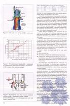
Figure 1. Schematic view of the old K-l combustor. Figure 2. NO emissions of standard K-l combustor as a function of pilot fuel percentage, normalised with nominal pilot fuel percentage. Figure 3. Sketch of the new pilot burners installed on the new K-l combustor: yellow is main premixed fuel; green is secondary premix fuel; and blue is subpilot fuel. Table 1. Operating conditions for NOx user defined model test diffusive and high temperature pilot flame, where approxi- mately 90% of the total NOx is generated. To quantify such dependence of emissions on pilot fuel, Figure 2 displays the trend...
Open the catalog to page 2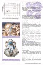
Figure 4. Comparison between measured and performed NO emissions in the three operating points studied. Figures 5 and 6. The GE 10-2 gas turbine rotor. load/temperature range and therefore changes its levels of emissions. For all of these operating points, CO emissions were negligible. The three different operating points corresponding to three different ambient temperatures were simulated, always at baseload conditions. Mass flows and composi- tions at main and pilot inlets differed slightly in each point, but the structure of the reactive flow field did not show sig- nificant variations. As...
Open the catalog to page 3All GE Gas Turbines catalogs and technical brochures
 LM6000
1 Page
 STEAM POWER SERVICES CATALOG
94 Pages
 NUCLEAR POWER PRODUCT CATALOG
28 Pages
 STEAM POWER PRODUCT CATALOG
61 Pages
 2018 POWER SERVICES CATALOG
111 Pages
 7E POWER PLANTS
1 Page
 LMS100®
7 Pages
 LMS100 POWER PLANTS
1 Page
 LM2500 POWER PLANTS
1 Page
 LM6000 POWER PLANTS
1 Page
 6B POWER PLANTS
2 Pages
 9E & GT13E2 POWER PLANTS
2 Pages
 6F POWER PLANTS
2 Pages
 7F POWER PLANTS
2 Pages
 9F.04, 9F.05, 9F.06
2 Pages
 Reciprocating Engines
2 Pages
 69663_aftermkt_bro
4 Pages
 1483_1112.indd
1 Page
 18900_5_15
8 Pages
 66535_reman_bro_redo_FINAL
6 Pages
 1212_1012
12 Pages
 Powering the world 2016
72 Pages
 raising the bar
8 Pages
 Waukesha* gas engines
12 Pages
 6 F. 01 Gas Turbine
4 Pages
 7HA.01 / .02 GAS TURBINE
2 Pages
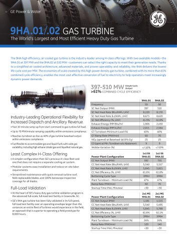 9HA.01 / .02 GAS TURBINE
2 Pages
 Dresser? Turbine Meters
8 Pages
 HSR line
6 Pages
 CNG In A Box? system
16 Pages
 Becker? T-Ball? Anti-Surge Valve
12 Pages
 Becker V0 Control Valves
12 Pages
 Ajax? E-565 Gas Engine
2 Pages
 7E.03 HDGT
15 Pages
 Baghouse Accessories
12 Pages
 Fabric Filter Bags & Cages
2 Pages
 GE10 15 ppm combustor
3 Pages
 GE10-1 Gas Turbine
8 Pages
 Frame 6 Gas Turbine
3 Pages
 GE10 Gas Turbine
6 Pages
 Heavy Duty Gas Turbine Products
24 Pages
 Product Structuring
5 Pages
 Gas Turbines Catalog
31 Pages


Archived catalogs
 7HA gas turbine
4 Pages
 9HA Gas turbine
4 Pages
- GE Vernova three-phase alternator
- GE Vernova power generation turbine
- GE Vernova steam turbine
- GE Vernova combined-cycle turbine
- GE Vernova aeroderivative turbine
- Single-shaft turbine
- Air cooled alternator
- Horizontal shaft turbine
- GE Vernova asynchronous alternator
- High-voltage alternator
- Compact alternator
- Power generation alternator
- Single-casing turbine
- Power plant alternator
- Water-cooled alternator
- Hydrogen-cooled alternator