- Catalogs
- GE Gas Turbines
- GE10 15 ppm combustor
GE10 15 ppm combustor
1 /3Pages

GE10 15 ppm combustor
1 /3Pages
Catalog excerpts
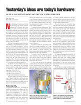
Yesterday’s ideas are today’s hardware GE OIL & GAS MEETING SHOWCASES THE NEW 15 PPM COMBUSTOR ERIC JEFFS AND KALYAN KALYANARAMAN ew Technology Frontiers was the title of GE Energy Oil & Gas customer meeting held in Florence, Italy, from Jan. 31-Feb. 1. The focus was on the technological challenges in developing oil and gas resources in remote parts of the world. “The challenges include production from nontraditional resources, drastically increased unit train size to leverage economies of scale, and operation with respect for the environment,” said Claudi Santiago, president of GE Energy’s Oil & Gas group. Last year’s meeting was mainly about new technologies for Liquified Natural Gas (LNG) and Gas-To-Liquids production, and the growing pressures on gas turbine operators to meet environmental standards set a decade earlier for the electric power industry. This year GE announced the commercialization of the 12 MW GE 10-2 gas turbine fitted with a new dry low NOx combustor. The twin-shaft turbine will be used predominantly as a mechanical drive. The new combustor will be adapted at the end of 2005 to the single-shaft GE 10-1 turbine used for generator drive. For the GE 10-2 fitted with the new combustor, GE is guaranteeing the following emission limits for a load range of 50 to 100% of baseload in a wide ambient temperature range from -20 to +100 °F: • 15 ppmvd (15% O2) for NOx • 25 ppmvd (15% O2) for CO • 15 ppmvd for unburned hydrocarbons The NOx limit for the old K-1 combustor was 25 ppmvd. And GE is offering the new combustor as a retrofit on existing PGT 10/A and GE 10-2 machines so that these units can meet new and future emission regulations. reducing the time the fuel-air mixture spends in the combustion primary zone (called the residence time). But all these actions increase CO and unburned hydrocarbons, and therefore designers try to achieve a balance in the levels of these pollutants. To promote efficient combustion at “lean” conditions, the fuel is “premixed” with air to produce an intimate mixture before it enters the combustion chamber. This also helps to avoid local hot spots that may produce thermal NOx. But this NOx reduction technique increases the chances of flame blow-out and combustion pressure dynamics, particularly at part-load and transient conditions. The premixed flames then need stabilizing solutions in the combustor. Around the world, new gas turbine installations are normally guaranteed at 25 ppm NOx. However, power generating plants generally function at constant frequency and hence constant speed, and at a steady output as determined by the system dispatcher. To achieve low-NOx operation over the wider operating range of the mechanical drive, GE has retained in the new combustor the variable geometry construction that was there in the older version. A valve in the air path to the combustor controls the fuel-air mixture by regulating the air flow to the primary zone. At high load, large quantities of air are employed to minimize NOx formation; at low loads the prima- ry air flow is partially blanked off. This optimizes the fuel/air ratio and reduces the velocity to give high combustion efficiency and low CO and unburned hydrocarbons. The air valve has two concentric rings with slots in the walls (Figure 1). The air flow out to the cooling path is controlled by the relative rotation of the rings which makes the slots overlap by a variable amount. Air which is not used for combustion is passed into the space between the inner liner and the outer wall of the can, to reduce metal temperatures and cool the combustion products before they enter the turbine. In the old K-1 combustor, the main premixed fuel was stabilized by pilot fuel that came in through 32 holes distributed circumferentially on the combustor throat. The nonpremixed pilot flames were diffusive, which means that the pilot fuel first came in contact with the air only inside the combustion chamber. These flames have hot spots and produce more thermal NOx. GE engineers estimated that about 90% of the total NOx in the old K-1 came from the diffusive pilot flame. The engineers added four premixed pilot burners and stabilized the pilot flame with a lean and diffusive sub-pilot flame (Figure 2). The result is that only a small fraction burns in a non-premixed mode as sub-pilot. The GE 10-2 has a single combustor which can be mounted either vertically or horizontally. Figure 1: The air valve is formed by two perforated rings which rotate relative to each other to open and close the air path Figure 2: Blue indicates the premixed pilot flame; green refers to the diffusive sub-pilot; yellow shows the premixed main flame Reducing NOx A significant part of the NOx in modern gas turbines is produced when nitrogen and oxygen in the combustion air react with each other above temperatures of 1,450 ºC. Designers of combustors try to lower this “thermal NOx” by adding more air in the primary combustion zone (lean combustion), thus lowering the flame temperature, and 10 Turbomachinery International • January/February 2005
Open the catalog to page 1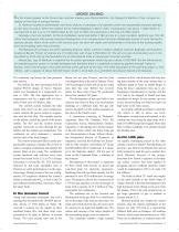
UPDATE ON IRAQ The first invited speaker at the Oil and Gas customer meeting was Ahmed Barifcani, the Deputy Oil Minister of Iraq. He gave an update on the Iraqi oil and gas industry Dr. Barifcani started his presentation with three pictures of sabotage of oil pipelines which has substantially thwarted attempts to raise Iraqi oil output. When the coalition forces entered Baghdad in March 2003, oil production was about 1 million bbl/d. It was planned to get it up to 3.8 million bbl/d by the end of 2004, but production is still only 2.8 million bbl/d. Sabotage is but one problem. All the oil installations...
Open the catalog to page 2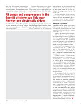
shore, and all pumps and compressors are electrically driven. The LNG plant and the associated 200 MW gas turbine power station is being built on an island, 3 km from the cen- The power plant consists of five LM6000 gas turbines in a Combined Heat and Power (CHP) scheme with a 50 MW back-up from the Norwegian National Grid. The HRSGs All pumps and compressors in the Snøvhit offshore gas field near Norway are electrically driven tre of Hammerfest. All the subsea equipment has been streamlined so as not to interfere with trawlers, since the area is the world’s largest pelagic fishery. 12 Turbomachinery...
Open the catalog to page 3All GE Gas Turbines catalogs and technical brochures
 LM6000
1 Page
 STEAM POWER SERVICES CATALOG
94 Pages
 NUCLEAR POWER PRODUCT CATALOG
28 Pages
 STEAM POWER PRODUCT CATALOG
61 Pages
 2018 POWER SERVICES CATALOG
111 Pages
 7E POWER PLANTS
1 Page
 LMS100®
7 Pages
 LMS100 POWER PLANTS
1 Page
 LM2500 POWER PLANTS
1 Page
 LM6000 POWER PLANTS
1 Page
 6B POWER PLANTS
2 Pages
 9E & GT13E2 POWER PLANTS
2 Pages
 6F POWER PLANTS
2 Pages
 7F POWER PLANTS
2 Pages
 9F.04, 9F.05, 9F.06
2 Pages
 Reciprocating Engines
2 Pages
 69663_aftermkt_bro
4 Pages
 1483_1112.indd
1 Page
 18900_5_15
8 Pages
 66535_reman_bro_redo_FINAL
6 Pages
 1212_1012
12 Pages
 Powering the world 2016
72 Pages
 raising the bar
8 Pages
 Waukesha* gas engines
12 Pages
 6 F. 01 Gas Turbine
4 Pages
 7HA.01 / .02 GAS TURBINE
2 Pages
 9HA.01 / .02 GAS TURBINE
2 Pages
 Dresser? Turbine Meters
8 Pages
 HSR line
6 Pages
 CNG In A Box? system
16 Pages
 Becker? T-Ball? Anti-Surge Valve
12 Pages
 Becker V0 Control Valves
12 Pages
 Ajax? E-565 Gas Engine
2 Pages
 7E.03 HDGT
15 Pages
 Baghouse Accessories
12 Pages
 Fabric Filter Bags & Cages
2 Pages
 GE10-1 Gas Turbine
8 Pages
 GE10-2 15 ppm combustor
3 Pages
 Frame 6 Gas Turbine
3 Pages
 GE10 Gas Turbine
6 Pages
 Heavy Duty Gas Turbine Products
24 Pages
 Product Structuring
5 Pages
 Gas Turbines Catalog
31 Pages


Archived catalogs
 7HA gas turbine
4 Pages
 9HA Gas turbine
4 Pages
- GE Vernova three-phase alternator
- GE Vernova power generation turbine
- GE Vernova steam turbine
- GE Vernova combined-cycle turbine
- GE Vernova aeroderivative turbine
- Single-shaft turbine
- Air cooled alternator
- Horizontal shaft turbine
- GE Vernova asynchronous alternator
- High-voltage alternator
- Compact alternator
- Power generation alternator
- Single-casing turbine
- Power plant alternator
- Water-cooled alternator
- Hydrogen-cooled alternator