

BR3-1-3

BR3-1-3
The high gate is designed for traffic control in areas with strict access control. It features a processor system, comb motion support, a two-way mechanism, diode pictograms, and emergency unlocking. The frame and rotor are made of stainless steel or powder-painted steel.
The rotor is constructed from 1.4301 ground stainless steel or S235JR powder-painted steel. The frame options include stainless steel, zinc-plated steel, or powder-painted steel. Access to the internal mechanism is secured with a key-operated lock and the gate is anchored to the floor.
The two-way mechanism allows traffic control in both or selected directions. Diode pictograms on the frame indicate the gate's locked/unlocked status, with a red cross for closure and a green arrow for opening. The electromechanical power motion ensures smooth passage and automatic arm locking.
The processor system controls the gate upon receiving a signal from an external device, managing arm motion and providing feedback after the transfer cycle. It is compatible with access control and RCP systems.
Upon receiving a command signal, the internal deadbolt unlocks for 10 seconds, indicated by the diode. The gate arm is pushed in the signaled direction, activating the power mechanism for passage. The system can memorize signals for alternate unlocking and can be operated with an additional switch.
- Power supply voltage: 24V
- Maximum power consumption: 120 VA
- Maximum current consumption: 5A
- Operation environment: -20°C to +50°C
- Weight: 250 kg
- Relative humidity: 10-80%
- IP rating: 34
- BR3-1-3-MMN: Powder-painted frame and roof, stainless steel rotor.
- BR3-1-3-ONN: Zinc-plated frame, stainless steel roof and rotor.
- BR3-1-3-NNN: Stainless steel frame, roof, and rotor.
- PS130 Transformer: 230/24V transformer with bus installation mode.
- Passage Counter: Displays the number of passage cycles.
- Voltage Back-Up Unit: Provides uninterrupted power supply with battery backup and optical signaling.
Catalog excerpts

HIGH GATE A high gate intended for traffic control, to be used in guarded areas of a strict access control level. It has a processor system, comb motion support, two-way mechanism, diode pictograms, emergency unlocking. The frame and the rotor are made of stainless steel or powder painted steel. The rotor is made of 1.4301 (EN 10088) ground stainless steel or S235JR powder painted steel (EN10025:1996). The frame is optionally made of: stainless steel / zinc plated steel / powder painted steel. The access to the gate internal mechanism is secured with a key- operated lock. Fastened to the floor with anchors, e.g. glued ones. The two-way mechanism enables traffic control in both directions or in a selected direction. The diode pictograms, situated on the gate frame, indicate the gate locked/unlocked status. The red cross indicates the passage closure, the green arrow indicates the passage opening. The electromechanical power motion of the arms facilitates smooth passing (traffic) and supports the automatic locking of the arm system. CONTROL SYSTEM After the processor system receives a signal from an external device (free of potential), it takes over a overall control of the system, i.e. enabling and disabling the arm motion, and sends the feedback signal after the transfer cycle is completed. The control system is prepared to work with access control systems and RCP systems. The mechanism is enabled after receiving a command signal from an external device. The internal dead bolt is electrically unlocked for the period of 10 seconds whereas the gate locked/ unlocked status is displayed on the diode indicator. After enabling the mechanism (which is signalled by the green arrow), the gate arm should be pushed in the signalled passage direction. After the gate arm is pushed, the power mechanism is automatically activated, facilitating the passing. After the movement is completed, the revolution is disabled until the time it receives another command signal. In case the system operates in both directions, the gate control chip software enables memorizing the signal from external devices with alternate unlocking of the dead bolt. The system can be operated with an additional switch, installed at the work place of a receptionist, guard, cashier ACCESS CONTROL SYSTEMS
Open the catalog to page 1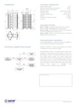
TECHNICAL PARAMETERS Power supply voltage Maximum power supply consumption Maximum current consumption Feedback signal Command signal Operation environment Environment relative humidity AVAILABLE OPTIONS BR3-1-3-MMN - Powder painted frame and roof. Rotor made of 1.4301 (EN 10088) ground stainless steel. BR3-1-3-ONN - Zinc plated frame. Roof and rotor made of 1.4301 (EN 10088) ground stainless steel. BR3-1-3-NNN - Frame, roof and rotor made of 1.4301 (EN 10088) ground stainless steel. SUPPLEMENTARY EQUIPMENT PS130 TRANSFORMER - a 230/24V transformer supplied in a safe casing. Bus installation...
Open the catalog to page 2


