
- Catalogs
- Gas Sensing Solutions (GSS)
- CO2 Sensor Evaluation Kit User Guide


CO2 Sensor Evaluation Kit User Guide

CO2 Sensor Evaluation Kit User Guide
The CO2 Sensor Evaluation Kit by Gas Sensing Solutions Ltd. includes a CO2 sensor and a USB cable with a sensor connector. This guide provides instructions for setting up and using the kit.
The software for the evaluation board can be downloaded from the GSS website. After downloading, unzip the file and run Setup.exe. A video tutorial is available for quick setup.
The USB cable has a USB-A connector and a 4-way connector for the sensor UART pins. Ensure correct positioning before connecting.
The USB cable includes a circuit for converting UART output to USB input. Windows may automatically install the driver, or it can be downloaded from the FTDI website.
After installation, the software can be started from the Start Menu. Connect to the sensor by selecting the correct COM port.
Select the sensor type and full-scale range. Measurements start automatically and are displayed graphically.
The software interface allows control of the sensor's UART functions. Modes include:
- Mode K1 Streaming Mode: Default mode for continuous measurement.
- Mode K0 Command Mode: Sensor is in sleep mode, awaiting commands.
- Mode K2 Polling Mode: Sensor reports readings upon request.
Methods for setting the sensor's zero point include:
- Zero in Nitrogen: Assumes a 0ppm CO2 environment.
- Zero in Fresh Air: Uses a default or user-defined CO2 concentration value.
- Zero in Known Gas Concentration: Adjusts based on a known CO2 concentration.
- ID: Returns sensor serial number and firmware version.
- Debug: Provides additional sensor settings information for troubleshooting.
The software allows full customization of sensor settings via UART commands.
Records sensor output to a text file with timestamps.
Provides troubleshooting steps for common issues such as no output or incorrect readings.
GSS products are subject to terms and conditions of sale, delivery, and payment.
Gas Sensing Solutions (GSS) guarantees the performance of its products according to the specifications valid at the time of shipment. GSS reserves the right to modify its products and specifications or discontinue any product or service without prior notice. Customers are advised to obtain the latest information from GSS to ensure accuracy.
GSS employs testing and quality control techniques as deemed necessary to support its warranty. However, specific testing of all parameters for each device is not conducted unless legally required. Customers must implement adequate design and operational safeguards to minimize risks associated with their applications.
GSS is not responsible for application assistance or customer product design. Customers are solely responsible for the selection and use of GSS products. GSS products are not intended for use in life support systems, nuclear systems, or any systems where malfunction could result in personal injury, death, or severe property or environmental damage. Any such use is at the customer's own risk.
GSS does not grant any licenses under its intellectual property rights for any combination, machine, or process involving its products or services. Reproduction of GSS datasheets is allowed only if unaltered and accompanied by all associated notices. GSS is not liable for unauthorized alterations or reliance on such information.
Any representations, warranties, or liabilities differing from those in this datasheet or GSS's standard terms are at the individual's own risk. GSS is not liable for such representations or reliance placed on them.
Gas Sensing Solutions Ltd., Grayshill Road, Cumbernauld, G68 9HQ, United Kingdom.
The document includes a revision history detailing updates and changes made to the user guide, with the latest revision being 1.4 on 09/06/2021.
Catalog excerpts

CO2 Sensor Evaluation Kit User Guide Gas Sensing Solutions Ltd. Page | 1 For regular updates, sign up at https://gassensing.co.uk Revision 1.3, 28 January 2021 Copyright © 2021 Gas Sensing Solutions Ltd.
Open the catalog to page 1
Gas Sensing Solutions Ltd. Page | 2 For regular updates, sign up at https://gassensing.co.uk Revision 1.3, 28 January 2021 Copyright © 2021 Gas Sensing Solutions Ltd.
Open the catalog to page 2
USER GUIDE INTRODUCTION The GSS CO2 sensor evaluation kit contains the following items. • CO2 sensor • USB cable with sensor connector SOFTWARE INSTALLATION The GSS evaluation board software is available direct from the GSS web site. Download the .zip file to your computer. Unzip and click on Setup.exe and follow the instructions on the screen. A short video showing how to get started with your evaluation kit and start taking readings in less than 2 minutes is available here: https://www.gassensing.co.uk/videos/ For more technical information on the sensor, download the appropriate data sheet...
Open the catalog to page 3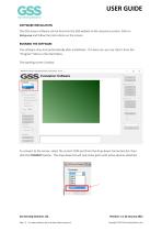
USER GUIDE SOFTWARE INSTALLATION The GSS sensor software can be found on the GSS website in the resources section. Click on Setup.exe and follow the instructions on the screen. RUNNING THE SOFTWARE The software may start automatically after installation. If it does not, you can start it from the “Program” Menu in the Start Menu. The opening screen is below. To connect to the sensor, select the correct COM port from the drop-down Connection list, then click the CONNECT button. The drop-down list will only show ports with active devices attached. Gas Sensing Solutions Ltd. Page | 4 For regular...
Open the catalog to page 4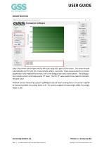
USER GUIDE SENSOR SELECTION Select the correct sensor type and the full-scale range (CO2 ppm) of the sensor. The sensor should automatically start to take CO2 measurements after 1-2 seconds. These measurements are shown graphically in the middle of the screen, and in the dialogue box (red) at the bottom. The dialogue box contains sensor serial data output (‘Z’ data). The CO2 ‘Z’ value needs to be scaled to calculate the ppm value. Ambient sensors measuring up to 1% (10000ppm) do not need a scaling factor, for sensors capable of measuring 0-60%, the scaling factor is 10. For sensors capable of...
Open the catalog to page 5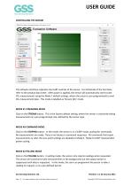
USER GUIDE CONTROLLING THE SENSOR The software interface replicates the UART controls of the sensor. For full details of the functions, refer to the product data sheet. After power is applied, the sensor will automatically start to take CO2 measurements using the Mode 1 default settings, where the sensor is pre-programmed to send CO2 measurement data. This mode is labelled as ‘Stream (K1)’ mode. MODE K1 STREAMING MODE Click on the STREAM button. This is the factory default setting, where the sensor is constantly taking measurements at a pre-programmed rate, defined by the sensor type. MODE K0...
Open the catalog to page 6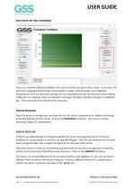
USER GUIDE ZERO-POINT SETTING COMMANDS There are a several methods available to the user to set the zero point of the sensor. In all cases, the best zero is obtained when the gas concentration is stable, and the sensor is at a stabilised temperature. Note the zero-point settings are not cumulative and only the latest zero-point setting is effective. For example, there is no benefit in zeroing in nitrogen, and then zeroing in a calibration gas. The sensor will store only the latest zero point. ZERO IN NITROGEN Place the sensor in nitrogen gas and allow time for the sensor temperature to stabilise...
Open the catalog to page 7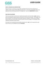
USER GUIDE ZERO IN A KNOWN GAS CONCENTRATION Place the sensor in a known gas concentration, and allow time for the sensor temperature to stabilise, and for the gas to be fully diffused into the sensor. Set the CO2 concentration value to the appropriate value by writing the value in the ‘set to’ box. Click on the KNOWN GAS (X) button. ZERO-POINT ADJUSTMENT If the CO2 concentration and the sensor reported concentration are known (both in ppm), the zero point can be adjusted using the known concentration to fine tune the zero point. For example, if the sensor has been in an environment that has...
Open the catalog to page 8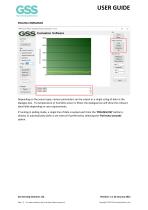
USER GUIDE POLLING COMMANDS Depending on the sensor type, various parameters can be output as a single string of data in the dialogue box. If a temperature or humidity sensor is fitted, the dialogue box will show the relevant data fields depending on user requirements. If running in polling mode, a single line of data is output each time the ‘POLLING (K2)’ button is clicked, or automatically within a set interval if preferred by selecting the ‘Poll every seconds’ option. Gas Sensing Solutions Ltd. Page | 9 For regular updates, sign up at https://gassensing.co.uk Revision 1.3, 28 January 2021...
Open the catalog to page 9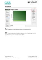
USER GUIDE INFO COMMANDS ID Clicking the ‘ID’ button will return the sensor serial number and firmware version. DEBUG Clicking the ‘Debug’ button will return additional information about the settings of the sensor. It is primarily intended to assist in remote debugging by GSS Ltd. Gas Sensing Solutions Ltd. Page | 10 For regular updates, sign up at https://gassensing.co.uk Revision 1.3, 28 January 2021 Copyright © 2021 Gas Sensing Solution
Open the catalog to page 10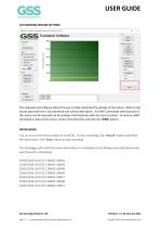
USER GUIDE CUSTOMISING SENSOR SETTINGS The evaluation kit software allows the user to fully customise the settings of the sensor. Refer to the sensor data sheet for a full command and control description. All UART commands and functions of the sensor can be manually set by writing in the blank box with the correct syntax. To send an UART command or data to the sensor, write in the blank box and click the ‘SEND’ button. DATALOGGER You can record the sensor output to a text file. To start recording, click ‘Record’ button and follow the instructions. Click ‘Stop’ button to stop recording. The datalogger...
Open the catalog to page 11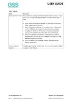
USER GUIDE FAULT FINDING Page | 12 For regular updates, sign up at https://gassensing.co.uk Copyright © 2021 Gas Sensing Solutions Ltd.
Open the catalog to page 12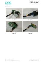
USER GUIDE EVK EXAMPLES Gas Sensing Solutions Ltd. Page | 13 For regular updates, sign up at https://gassensing.co.uk Revision 1.3, 28 January 2021 Copyright © 2021 Gas Sensing Solutions Lt
Open the catalog to page 13All Gas Sensing Solutions (GSS) catalogs and technical brochures
 Auto-Zero Setting CO2 Sensor
9 Pages
 CO2 Sensor Response Time
12 Pages
 RoHS and REACH Compliance
9 Pages
 Zeroing a CO2 Sensor
11 Pages
 SprintIR-W Data Sheet
36 Pages
 SprintIR-R Data Sheet
31 Pages
 SprintIR-6S Data Sheet
31 Pages
 ExplorIR-W Data Sheet
33 Pages
 What is fresh Air
7 Pages
 ExplorIR-M Data Sheet
28 Pages
 CozIR-LP3 Data Sheet
53 Pages
 CozIR-A Product Flyer
2 Pages
 CozIR-LP2 Data Sheet
40 Pages
 CozIR-LP Data Sheet
29 Pages
 CozIR-A Data Sheet
32 Pages
 CozIR-Blink Data Sheet
37 Pages
 SprintIR-W Product Flyer
2 Pages
 SprintIR-R Product Flyer
2 Pages
 SprintIR-6S Product Flyer
2 Pages
 ExplorIR-W Product Flyer
2 Pages
 ExplorIR-M Product Flyer
2 Pages
 EvaluatIR-M Product Flyer
2 Pages
 EvaluatIR-A Product Flyer
2 Pages
 CozIR-LP3 Product Flyer
2 Pages
 CozIR-LP2 Product Flyer
2 Pages
 CozIR-LP Product Flyer
2 Pages
 CozIR-Blink Product Flyer
2 Pages


