
- Catalogs
- Galltec Mess- und Regeltechnik GmbH
- A and B Series

- Company
- Products
- Catalogs
- News & Trends
- Exhibitions
A and B Series
1 /10Pages
A and B Series
1 /10Pages
Catalog excerpts

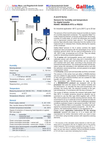
Galltec Mess- und Regeltechnik GmbH D-71145 Bondorf ■ Germany E-Mail: [email protected] ■ Internet:www.galltec-mela.de Humidity Sensing element FE09 Power supply, external 5...30 V DC Ambient temperature transmitter -40...85°C Degree of protection of measuring head depends on applied filter (see page 2) measuring head (see table) connector sensor part ---> transmitter IP67 Power consumption transmitter <0.88 mA Power consumption transmitter + sensor part <1.95 mA Power consumption transmitter + sensor part + display < 2.10 mA Directive about electromagnetic compatibility 2014/30/EU Sensors for humidity and temperature The sensors of the A and B series measure humidity by means of a humidity-dependant condenser. The capacitive Mela® humidity measuring element, produced using thinfilm technology, consists of a base plate, on which the electrodes are housed and a hygroscopic polymer layer above it. The hygroscopic polymer layer absorbs water molecules from the medium to be measured (air) or releases them, thereby altering the capacity of the condenser. Galltec+Mela® sensors in the A series combine the digital measured value processing with the advantages of our robust industrial sensors which can be used at temperatures up to -80...200°C resp. at pressures up to 25 bar. They are ideally suited for demanding industrial applications. The A series with exchangeable sensor part consists of a calibrated sensor part with 4-pin plug and a transmitter with digital output. Sensor part and transmitter can be combined and matched with each other, according to the physical and mechanical requirements. The measured humidity and temperature values are calculated in the calibrated sensor part with the calibration values stored there, and are passed on as digital measurement values. In the B series, sensor part and transmitter are firmly connected. The sensors in this series have got either a RS485-interface and are suitable for data transfer via MODBUS-RTU protocol or they have got a RS232-interface and are suitable for data transfer via ASCII protocol. The transmitters with RS485-interface for data transfer of a MODBUS-RTU protocol are equipped with an hx processor that uses the values of the relative humidity and the temperature to calculate the dew point temperature, the enthalpy, the mixing ratio, the absolute humidity or the wet-bulb temperature, in accordance with the laws of physics 1). The scope of delivery includes the sintered high-grade steel filter ZE13. If a better dynamics should be required, we recommend to use the filter type ZE04 together with a PTFE filter which protects the humidity sensing element directly. We recommend to do so in particular at low air speeds and also its increased service life, even under more challenging operating conditions (pollutant impact or permanent humidity > 95 %rh). The use of different filters is not possible. The sensors are designed for unpressurised systems (except the ...0D, ED, HD... version), the measurement medium is non-aggressive air. Please consult ..application instructions for the sensing elements" (product info sheet no. A 1) or check with the manufacturer for further information which you need to bear in mind when using humidity sensors with capacitive sensing elements. 11 The accuracy of the calculated values depends on both the operating point in accordance with the hx diagram and on the primary values measured. The hx processor operates in the range -30 °C < T < +70 °C, 5 % rh<F<95 % rh. Values outside this range are not calculated, the last valid value is displayed. Normal atmospheric pressure of 1013.25 mbar is used when calculating the hx values. A and B series, digital page 1 of 10
Open the catalog to page 1
Galltec+Mela A and B series, digital page 2 of 10
Open the catalog to page 2
Mounting and user information Mounting position Install the sensor at a place where characteristic levels of humidity occur. Avoid installation next to heaters, doors or on outer walls. Avoid places exposed to the sun. The position the sensor is mounted in (horizontal, vertical) does not matter. However, it should be mounted in such a way that no water can get into it. We recommend that you lay the connection lines in a loop so that any water that may be present can run off. Please note the maximum permissible ambient temperature for the sensor part and transmitter when installing it. The electrical...
Open the catalog to page 3
Dimensions A Series clamping range Ø 3...7 Dimensions of clearance holes 2 x Ø4.8 measuring head exchangeable connector with 4-pin plug connector with 4-pin plug special teflon cable special teflon cable AWK... with SVKA.00... for wall mounting -40...85 °C Ømax.19 measuring head AWK... with SZKA.HD... sensor part up to 160 °C and 25 bar AWK... with SZKA.0H... sensor part up to 200 °C clamping range Ø 3...7 measuring head exchangeable AKK... with SVKA.0E... for duct mounting up to 150 °C Galltec+Mela A and B series, digital page 4 of 10 insulation distance e.g. insulated wall or air (-40 ... 85...
Open the catalog to page 4
Dimensions of clearance holes 2 x 04.8 BZxx.OH... sensor part up to 200 °C clamping range BKxx.OE... for duct mounting up to 150 °C insulation distance (for high temp. applications up to max. 50°C) __243 BKxx.TH... for duct mounting up to 200 °C A and B series, digital page 5 of 10
Open the catalog to page 5
The following parameters are possible for data transfer via the RS485 interface : Table 1 - Modbus register The word order of data types which extend over several Modbus registers is Little Endian. This means that the low byte word is in the lower register and the high byte word is in the higher register. The measured values for relative humidity, temperature and the corresponding alarm codes, along with the probe serial number, are transferred continuously to the transmitter and saved in registers 0...7. Sensors with a screen show both measured values. If one of the two alarm codes is not working...
Open the catalog to page 6
Table 2 lists all the possible alarm register values when measuring temperature (reg. no. 2). Table 4 - alarm codes hx processor The Modbus address can be modified at any time via write access to the address register (reg. no. 205). Permissible slave addresses are within the 1...247 range. Using address 0 as a slave address is not permissible. Addresses within the 248...255 range are reserved for special Modbus services and their use as a slave address is not permissible either. Address 1 is pre-defined. In standard mode (and in the network if required), the Modbus address for all sensors can...
Open the catalog to page 7All Galltec Mess- und Regeltechnik GmbH catalogs and technical brochures
 Productcatalog 2025
109 Pages
 D Series
6 Pages
 M-Series
3 Pages
 Product overview
15 Pages
 eStat20 DUO
10 Pages
Archived catalogs
 Humidistats
2 Pages

- Digital temperature control
- Temperature controller
- Galltec Mess- und Regeltechnik humidity and temperature sensor
- Digital temperature controller
- Galltec Mess- und Regeltechnik relative humidity and temperature sensor
- PID temperature control
- Galltec Mess- und Regeltechnik waterproof humidity and temperature sensor
- PID temperature controller
- Galltec Mess- und Regeltechnik digital humidity and temperature sensor
- Galltec Mess- und Regeltechnik analog humidity and temperature sensor
- Galltec Mess- und Regeltechnik DC humidity and temperature sensor
- Galltec Mess- und Regeltechnik wall-mount humidity and temperature sensor
- Galltec Mess- und Regeltechnik air humidity and temperature sensor
- Heating temperature controller
- Galltec Mess- und Regeltechnik humidity and temperature sensor for industrial applications
- Galltec Mess- und Regeltechnik 24VDC humidity and temperature sensor
- Galltec Mess- und Regeltechnik IP65 humidity and temperature sensor
- Galltec Mess- und Regeltechnik humidity and temperature sensor for process applications
- Relative humidity probe