

FYH UNIT BEARINGS

FYH UNIT BEARINGS
- Corrosion Resistance: Special coatings extend the life of the bearing by resisting corrosion.
- Installation and Handling: FYH Ball Bearing Units are designed for simple installation without the need for additional lubrication or seal installation, reducing handling and downtime.
- Locking Mechanisms: Four types of locking mechanisms are available: set screw, eccentric locking collar, tapered adapter, and concentric roller.
- Dust Resistant Series: Includes triple lip seal inserts and units with covers for protection against dust, water, and debris.
- Heat and Cold Resistant Series: Designed to withstand extreme temperatures.
- Corrosion Resistant Series: Available in stainless, plastic, and nickel-plated units.
- Tougher Casting Series: Features cast steel and ductile iron housings.
- Compact and Lightweight Series: Includes small die-cast and lightweight casting units.
- Special Environment Series: Suitable for severe environments, exposure to water, chemicals, high temperature, or high speed.
- Air Handling Series: Includes S3 & S5 bearing units and NU-LOC units.
The document outlines various materials and types of iron used in manufacturing, such as high strength ductile iron, cast iron, stainless steel, and thermoplastic. It also mentions different types of brackets and frames, including flange brackets and steel plate frames, highlighting their specific applications and properties.
FYH ball bearing units require minimal maintenance under general conditions. Regular checks are recommended based on the operating environment. Bearings in clean, low-load environments need less frequent checks compared to those in dirty, high-load settings. Proper lubrication and the use of appropriate grease are crucial. For environments with high axial loads, shouldered shafts are advised, and for wet or dusty conditions, covers or specific inserts are recommended.
Bearing life is determined by material fatigue and lubricant degradation. Proper lubrication can extend bearing life. The basic rating life is calculated based on the load and operating conditions, with formulas provided for precise calculations. The document also discusses the correction of load ratings due to temperature changes and the factors affecting the corrected rating life, including reliability, bearing characterization, and operating conditions.
The grease life of ball bearing units is influenced by load, speed, and temperature. A formula is provided to calculate grease life under specific conditions, with guidelines for temperature and speed limits. The document includes a reference figure illustrating the relationship between grease life, bearing load, speed, and temperature.
Loads on bearings come from various sources, including the weight of components and dynamic forces from belts and chains. The document provides methods to calculate these loads, considering factors like vibration and impact. It includes formulas for calculating loads from belts, chains, and gear transmissions, with specific factors for different belt types and gear arrangements.
The document provides detailed formulas and procedures for calculating synthetic loads applied to gears, including tangential and radial load components. It emphasizes the importance of considering load factors for vibration and impact, as well as gear factors for machining accuracy.
Methods for determining radial load distribution across bearings are outlined, with emphasis on accounting for axial load components. The document provides formulas for calculating dynamic equivalent loads, considering both radial and axial components.
The document explains how to calculate dynamic equivalent radial loads and average dynamic loads under fluctuating conditions. It also covers basic static load ratings and static equivalent loads, highlighting the importance of safety factors in bearing applications.
Several examples illustrate the application of formulas to real-world scenarios, such as distributing loads across bearings, calculating dynamic equivalent loads, and selecting appropriate bearing units based on load and life requirements.
Guidelines for calculating grease life and bearing life under various conditions, including high temperature and non-lubrication scenarios, are provided. The document stresses the need for regular lubrication and appropriate bearing selection to ensure longevity.
The document concludes with a discussion on the allowable rotating speeds of bearings, which are influenced by factors such as bearing dimensions, seal type, and inner ring fit. Standard values for allowable speeds are provided in a table.
The document outlines various types of bearings and blowers, including standard, heat-resistant, and cold-resistant types. It specifies different series and codes for each type, such as D1K2 for heat-resistant and D2K2 for cold-resistant bearings. High-speed blowers are also mentioned with specific codes like S5.
The allowable rotational speed of bearing units is influenced by factors such as fitting and temperature. The document provides a table (Table 6.2) with fitting factors for different types of ball bearing units, which are used to adjust the maximum allowable speed. It also discusses the impact of operating temperature on bearing specifications, emphasizing the need for appropriate grease and internal clearance adjustments.
The document details the strength characteristics of various housing materials, including cast iron, ductile cast iron, cast steel, stamped steel, stainless steel, and die-cast zinc alloy. It provides safety factors for each material type under different load conditions (static, vibration, impact) and includes figures illustrating the static rupture strength of different housing designs.
- Table 6.2: Fitting factor of ball bearing units.
- Table 8.1: Safety factor of gray cast iron products.
- Table 8.2: Safety factor of ductile cast iron.
- Table 8.3: Safety factor of cast steel products.
- Table 8.4: Allowable load of stamped steel housings.
- Table 8.5: Safety factor of stainless steel products.
- Table 8.6: Safety factor of zinc alloy die-cast products.
- Figures illustrate static rupture strength for various housing types, including pillow, flange, and take-up types.
The document recommends selecting the appropriate bearing type based on operational temperature and load conditions. It emphasizes the importance of considering fitting factors and safety factors to ensure optimal performance and durability of the bearing units and housings.
- Proper shaft selection is crucial for optimal performance and maintenance-free operation of ball bearing units.
- Dimensional tolerances vary based on the type of bearing and operational conditions, such as speed and load.
- Tables 9.1 to 9.5 provide detailed tolerance guidelines for different shaft and bearing configurations.
- Shouldered shafts are recommended for high axial loads, vibration, or impact.
- Table 9.6 outlines the recommended shoulder diameter and fillet radius for shouldered shafts.
- In high temperature scenarios, one bearing should be fixed while the other is free to float to accommodate shaft expansion.
- Formula 9.1 calculates shaft expansion due to temperature changes.
- Insufficient rigidity or poor flatness of the mounting base can lead to vibration and premature bearing failure.
- Fig. 9.3 provides recommended flatness values for mounting surfaces.
- Cartridge units are suitable for high vibration or speed applications, allowing axial movement within the mounting bore.
- Table 9.8 specifies dimensional requirements for cylindrical bores.
- Take-up units allow linear adjustment and are positioned between guide rails.
- Table 9.9 provides dimensions for guide rails and adjuster bolts.
- Dowel pins ensure accurate positioning of housings on the mounting base.
- Dimensions for dowel pins are available in Appendix table 5.
- FYH Ball Bearing Units conform to JIS B 1557 standards.
- Nomenclature includes model codes, diameter series, bore diameter, and special codes.
- Tables 10.1 and 10.2 provide details on bearing and housing model codes.
This section lists various flange types and their corresponding codes, such as FB for three-bolt flange type and FS for square four-bolt cartridge flange type. Each type is specified by its shape and material, including options like stainless steel and thermoplastic series.
Tables provide codes for diameter series and bore diameters, detailing sizes from small light-duty to heavy-duty applications. Bore diameter codes specify nominal sizes in millimeters and inches.
Fitting codes indicate tolerance classes for spherical bores, while accessory codes describe cover types and seal options. These codes help in selecting the appropriate components for specific applications.
Special codes for bearings and housings include grease types, set screw designs, and sealing devices. Housing codes specify thread types and positions, machining details, and material options like stainless steel and ductile iron.
Accuracy standards for ball bearing units are outlined, conforming to JIS standards. Tables detail tolerances for inner and outer rings, including variations for special applications like blowers. Internal clearance is crucial for operational life and is specified for different conditions.
Bearing materials include high carbon chrome steel for strength and durability, with stainless steel options for corrosion resistance. Housing materials range from gray cast iron to ductile iron and cast carbon steel, each chosen for specific mechanical properties.
Tables list chemical components and mechanical properties of materials used in bearings and housings, ensuring they meet required standards for performance and durability.
Several tables outline the mechanical properties of various materials used in manufacturing. For instance, carbon steel cast products (SC450) have a yielding point of 225 N/mm² or more and a tensile strength of 450 N/mm² or more. The elongation is 19% or more, and the reduction is 30% or more. Similarly, the mechanical properties of cast carbon steel products (JIS G 3101) and zinc alloy die-cast (ZDC02) are detailed, providing essential data for material selection in engineering applications.
Table 12.10 lists materials used in ball bearing units, including nitrile rubber for standard seals and silicone rubber for heat and cold-resistant seals. Various steel types, such as SPCC and SUS304, are used for slingers and covers, while chrome molybdenum steel (SCM435) is used for hexagon socket set screws.
The document discusses the performance of bearings, focusing on friction torque and temperature increase. Friction torque is influenced by bearing model, dimensions, load, speed, and lubrication. Temperature increase is related to friction torque and environmental conditions. Graphs illustrate the relationship between rotating speed and friction torque, as well as temperature changes during operation.
Tests are conducted to evaluate the dustproof and waterproof performance of bearings. The dust sprinkle rotating test and dust immersion rotating test show that triple-lip bearings and covered units exhibit superior performance compared to standard single-lip bearings. The waterproof test indicates that triple-lip and covered units resist rust better than standard units.
Proper handling and installation of FYH Bearings are crucial for reliable performance. The document provides detailed procedures for installing setscrew and adapter style units, emphasizing the importance of correct torque settings and alignment. Various set screw styles, such as Bullet Point and Double Point, are available to suit different applications.
- Use a torque wrench to tighten bolts and locknuts to specified settings. Refer to Appendix tables for torque specifications.
- For pillow block housings, adjust axially while rotating the shaft, then re-tighten bolts. For flange block housings, ensure correct axial alignment before installation.
- Bend a washer tab into a locknut slot to secure it.
- Ensure the shaft rotates smoothly after installation.
- Inspect the unit for base rigidity, surface flatness, and shaft tolerance.
- Slide the bearing onto the shaft, align it, and secure with bolts using a torque wrench.
- Fit and rotate the eccentric locking collar, then tighten the setscrew.
- Ensure smooth shaft rotation after installation.
- Apply grease to the cover's seal lip and internal space.
- Secure the bearing unit, slide the cover over the shaft, and press it into place.
- For steel covers, use a mallet to avoid deformation; for cast iron covers, use bolts.
- Check for abnormalities and ensure smooth shaft rotation.
- Ensure smooth rotation by hand; check for resistance or uneven torque.
- Conduct powered runs to check for noise, vibration, and temperature changes.
- Refer to Table 14.2 for common faults and causes during test runs.
- Inspect external appearance, set screws, noise, temperature, and grease levels.
- Immediate action is required if faults are found to prevent further damage.
- Refer to Table 14.3 for common faults and causes during periodic inspections.
- High-quality grease is supplied; re-greasing schedules depend on operating conditions.
- Use recommended grease types and adhere to specified intervals and amounts.
- Refer to Table 14.4 for grease schedules and Table 14.5 for recommended grease amounts.
- If the housing is intact, only the bearing insert needs replacement.
- Inspect the housing for damage before inserting a new bearing.
- Remove the bearing unit from the shaft and mounting base.
- Screw in the set screws so that they do not protrude outside the inner ring's outer diameter to avoid damage to the bearing seat.
- Rotate the bearing 90º using a bar or pipe until it is horizontal.
- Remove the bearing insert from the housing via the loading slot.
- Reverse the procedure to install a new bearing insert, ensuring set screws are in place before proceeding.
- The document provides detailed dimensional tables for various types of ball bearing units, including pillow type, square four-bolt flange type, oval flange type, round flange cartridge type, stamped steel plate flange type, take-up type, and other units.
- Each type is categorized by specific models and dimensions, such as UCP, NAP, UKP, and others, with varying shaft diameters and specifications.
- Corrosion-resistant series and lightweight options are also detailed, indicating their specific applications and material compositions.
- Variations in tolerance for the distance from the mounting bottom to the center of the spherical bore are specified for different housing numbers.
- Specific dimensions and forms for housing with cast iron covers are provided, such as H2c dimensions for models P204JE3 and P205JE3.
- Standard bolt sizes and basic factors for load ratings are included for each unit type.
- Part numbers and fitting codes follow bore diameter numbers, with specific grease fitting part numbers provided for different models.
- Triple seal type products have accessory codes following the part number of the unit or bearing.
- Housings of nodular graphite cast iron are available as an option.
The document provides detailed specifications for bolt hole positions, circumferential runout tolerances, and variations in bolt hole diameters for various housing numbers. Units are measured in millimeters.
- FS305 to FS328: Tolerances for spigot joint outside diameter and bolt hole positions are specified, with variations ranging from 0 to -0.089 mm.
- FS305 to FS315: Bolt hole diameter tolerance is ±0.2 mm, while FS316 to FS328 is ±0.3 mm.
The document includes a comprehensive table listing shaft diameters, dimensions, bolt sizes, and load ratings for different unit numbers. It specifies both open and closed types, with mass and load ratings provided in kN.
- Housings are available in nodular graphite cast iron.
- Units with cast iron covers and stainless steel covers are detailed, including variations in tolerance for distance from mounting surfaces and bolt hole positions.
- Part numbers for grease fittings and adapters are provided, with specific codes following bore diameter numbers.
- Triple seal type products have accessory codes that follow the part number.
Additional remarks include fitting codes for units with covers and applicable grease fitting part numbers. The document also references dimensional tables for further details on bearings and adapters.
The document provides detailed specifications for various bearing units, including dimensions, load ratings, and fitting codes. It covers a range of shaft diameters from 20 mm to 100 mm, with specific details on bolt sizes, housing numbers, and mass.
Instructions are given for fitting codes that follow bore diameter numbers, applicable grease fittings, and the use of accessory codes for triple seal type products. The document also references dimensional tables for applicable bearings.
The document outlines variations in tolerance for spigot joint outside diameter, distance from mounting surface to center of spherical bore, bolt hole position, and circumferential runout. Tolerances for bolt hole diameters are also specified.
It is recommended to refer to Table 10.5 for fitting codes and to use nodular graphite cast iron housings where applicable. The document suggests checking dimensional tables for detailed bearing forms.
Tables provide comprehensive data on dimensions, bolt sizes, and load ratings for different housing numbers. Specific tolerances and variations are listed for each housing type, ensuring precise fitting and performance.
Important details include the range of shaft diameters, specific fitting codes, and the availability of housings in different materials. The document emphasizes the importance of adhering to specified tolerances for optimal performance.
The document provides detailed specifications for various bearing units and adapters, including dimensions, load ratings, and mass. Key specifications include shaft diameters ranging from 20 mm to 90 mm, with corresponding load ratings and mass details for each unit.
The document outlines the use of tapered bore adapters and cylindrical bore bearings with set screws. It specifies the part numbers for units with adapters and provides examples of how to combine part numbers for specific configurations.
The document adheres to standard dimensions and load ratings for bearing units, ensuring compatibility and interchangeability within the UK200 and H300X series. It also mentions the availability of inch bore diameter series adapters.
Recommendations include selecting the appropriate adapter series for specific bearing units and considering the double seal type product for enhanced protection. The document also suggests checking the dimensional tables for compatibility and additional options.
The tables provide comprehensive data on dimensions, load ratings, and mass for each bearing unit and adapter. For example, the UK205 unit is a double seal type with a load rating of 14.0 kN and a mass of 0.16 kg. The tables also include information on set screw dimensions and applicable adapter series.
- Bore and Shaft Diameter: The bore diameter ranges from 12 mm to 55 mm, with corresponding shaft diameters.
- Load Ratings: Basic load ratings are provided in kN for each bearing type.
- Dimensions: Detailed dimensions are given for each bearing, including bore (d), outer diameter (D), width (B), and corner radius (r).
- Set Screw and Mass: Information on set screw sizes and the mass of each bearing is included.
- Installation: Bearings are designed for easy installation with eccentric locking collars.
- Maintenance: Regular inspection and lubrication are recommended to ensure optimal performance.
- Bearings conform to industry standards for dimensions and load ratings.
- Set screws and locking collars are standardized for compatibility.
- Choose the appropriate bearing size based on shaft diameter and load requirements.
- Ensure proper installation to prevent misalignment and wear.
- Tables provide comprehensive data on dimensions, load ratings, and part numbers for various bearing types.
- Adapter sleeves, lock nuts, and washers are listed with corresponding dimensions and part numbers.
The document provides detailed specifications for steel plate covers and cast iron covers used in UK and UC type bearings. It includes part numbers based on shaft diameters and bearing numbers, with distinctions between open and sealed types. For example, a steel plate cover for a UK205 bearing with a 20 mm shaft diameter is designated as C−5×20 for open type and D−5 for sealed type.
Instructions for selecting the appropriate cover based on shaft diameter and bearing type are outlined. The document also details the nominal codes and dimensions for grease fittings, Allen key wrenches, and reducing sockets, providing measurements in millimeters.
Recommended tightening torques for various components, including housing and cast iron cover mounting bolts, are provided. These are specified for different nominal screw sizes and are crucial for ensuring proper assembly and function.
Examples of use for FYH ball bearing units are listed, highlighting their versatility in various machines and equipment such as conveyors, woodworking machines, and wastewater treatment facilities.
The appendix includes tables with additional technical data, such as tightening torques for different components, machining dimensions for housing dowel pins, and conversion charts for units and material properties.
The document provides detailed specifications for various bearing units, including dimensions such as bearing surface diameter, width across flats, width across corners, and height. These specifications are crucial for selecting the appropriate bearing unit for specific applications.
Appendix Table 18 offers a comprehensive comparison of part numbers by manufacturers for different types of bearing units, including pillow type, flange type, take-up type, and others. This section helps in identifying equivalent products across different brands.
The document highlights special specification items such as heat and cold-resistant grease, non-contact and lubricated types, and ductile cast iron options. It also mentions high-temperature capabilities of certain units and the use of Silicon Nitride ceramic balls for extreme environments.
FYH Air Handling units are designed for demanding HVAC applications, featuring reduced noise and vibration for high-speed operations. Corrosion-resistant units are available in various sizes and styles, ensuring compliance with federal standards.
The document provides contact details for Nippon Pillow Block Co., Ltd., including their head office, overseas division, and domestic branches in Japan. This information is essential for inquiries and further assistance.
Priority is given to the nominal sizes of screws without parentheses, and the document includes a note on the width of the outer ring for certain items differing from others.
Catalog excerpts

® ® BALL BEARING UNITS BALL BEARING UNITS ® fyhbea rin g om s.c CAT.NO.3310 NIPPON PILLOW BLOCK CO.,LTD. CAT.No.3310 2010.07.20000DS NIPPON PILLOW BLOCK CO.,LTD.
Open the catalog to page 1
Problems with corrosion? CORROSION RESISTANT UNITS The corrosion resistant series is available in a wide array of sizes and styles, and units may be customized with a number of dierent specialized options to accommodate virtually any application. Federal compliance can be assured with FYH Bearing Units. (Page 21) Looking for high speed? AIR HANDLING UNITS FYH Air Handling units are designed for a wide range of highly demanding HVAC applications. The tighter C2 internal ball clearance reduces noise and vibration in high speed applications. Our original “Bullet Point” set screw is designed so that...
Open the catalog to page 2
Ball Bearing Units (contents)
Open the catalog to page 3
1 Structure and features FYH Ball Bearing Units are manufactured to exacting standards comprising grease sealed deep groove ball bearings and housings in various forms. Self-aligning units allow for easy installation and are supplied with grease fittings in order to facilitate quick and convenient re-lubrication. 1.1 Structure FYH Ball Bearing Units are constructed of high-carbon chromium bearing steel and have precision honed raceways and riveted steel cages (Fig. 1.1). Grease fitting Outer ring with spherical outside surface Grease hole Slinger Seal Ball and cage Wide inner ring Hexagon socket...
Open the catalog to page 7
1 Structure and features 3 Superior sealing performance 1.2 Features FYH Ball Bearing Units have many features and are available in various models. A wide selection of mounted units is offered to fit virtually any application. 1 Supreme load capacity and accuracy FYH Ball Bearing Units feature an internal structure identical to single row deep groove ball bearings can and bear significant radial load, as well as a great deal of axial load in both directions. The hardened steel balls exhibit a high degree of “roundness” and the races are highly polished to accommodate a smooth ride at a wide range...
Open the catalog to page 8
4 Simple lubrication FYH Ball Bearing Units are tapped to accept a grease fitting which is also supplied with every mounted unit. Bearings are pre-lubricated at the factory and do not require additional grease upon installation. When operating in excessively moist, dusty, or hot environments it is recommended that grease be supplied at regular intervals. If appropriately maintained, the rated life of the bearing can be extended. The grease fittings that are supplied with FYH mounted units include 1/4-28 for smaller units and 1/8 PT for larger units. Additional styles are available upon request....
Open the catalog to page 9
2 Models 2 Models 2.1 Model list Table 2.1 and Table 2.2 show the models of FYH Ball Bearing Units and ball bearing inserts. Table 2.1 Model Type FYH Ball Bearing Units models Bearing bore dia. Surface (fixing to shaft) Shaft dia. (mm) Dimension table /2 − 4 12 − 140 P.72 /2 − 2 15/16 12 − 75 P.78 /2 − 2 15/16 12 − 75 P.80 /4 − 2 7/16 20 − 60 P.82 /4 − 4 1/2 20 − 125 P.84 /8 − 4 25 − 140 P.90 /4 − 4 1/2 Model code (inch) 1 NAP 1 1 Cylindrical bore (with concentric locking collar) NCP 3 Tapered bore UKP 3 Cylindrical bore (with set screws) UCP-sc 7 Tapered bore (2) Cast steel type UCP NAPK (1)...
Open the catalog to page 10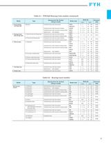
Table 2.1 Model 4 Round ange cartridge type Type Standard FYH Ball Bearing Units models (continued) Bearing bore dia. Surface (fixing to shaft) Cylindrical bore (with set screws) Shaft dia. Model code UCFC (inch) 12 − 100 P.202 1−4 25 − 100 P.206 /8 − 2 3/16 25 − 55 P.208 /4 − 2 7/16 20 − 60 P.210 /4 − 3 1/2 20 − 90 P.212 /2 − 1 7/16 12 − 35 P.216 /2 − 1 7/16 12 − 35 P.218 /2 − 4 12 − 140 P.220 /2 − 3 7/16 12 − 85 P.226 /2 − 2 15/16 12 − 75 P.230 /4 − 2 7/16 20 − 60 P.232 /4 − 2 7/16 20 − 60 P.234 /4 − 4 1/2 20 − 125 P.236 /4 − 2 20 − 50 P.242 /4 − 2 20 − 50 P.244 /2 − 2 1/2 12 − 65 P.246 Cylindrical...
Open the catalog to page 11
2 Models Note 1) Descriptions of codes for units with covers are shown in the table below. (common to all the models) 2.2 Models and features Diameter series FYH Ball Bearing Units are available in a variety of styles and sizes. Models and features of the Ball Bearing Units are shown below. 2 Code C, CD Descriptions Stamped steel plate cover type FC, FCD Cast iron cover type X C, CD From X05 to X17: stamped steel plate cover type X18 and X20: cast iron cover type 3 C, CD Cast iron cover type 1 Pillow type units 1 Pillow type units: P.72 UCP 2 Thick pillow type units: P.98 UKP UCIP UKIP Cylindrical...
Open the catalog to page 12
4 High centerheight pillow type units: P. 110 Cylindrical bore (with set screws) 5 Lightweight pillow type units: P.112 Cylindrical bore (with set screw locking) Cylindrical bore (with eccentric locking collar) 6 Lightweight (die-cast) pillow type units: P.114 Cylindrical bore (with set screws) C, CD: Rubber coating cover 7 Corrosion resistant series pillow type units: P.116 Cylindrical bore (with set screws) C, CD: Stainless steel plate cover Lightweight type C, CD: Rubber coating cover 8 Steel plate pillow type units: P. 126 SBPP SAPP Cylindrical bore (with set screw locking) Cylindrical bore...
Open the catalog to page 13
2 Models 2 Square four-bolt flange type units 1 Square four-bolt flange type units: P.128 UCF UCF-E NANF UKF NCF NCF-E Cylindrical bore (with set screws) L3 C, D (FC, FD)1) Cylindrical bore (with eccentric locking collar) Cylindrical bore (with concentric locking collar) Tapered bore (with adapter) L3 C, D (FC, FD)1) 3 Corrosion resistant series square four-bolt flange type units: P.154 UCSF-H1S6 UCSF-EH1S6 UCVF-S6 Cylindrical bore (with set screws) C, D: Stainless steel plate cover C, D: Plastic cover UCVF-ES7 3 Oval flange type units 1 Oval two-bolt flange type units: P.162 2 Square four-bolt...
Open the catalog to page 14
2 Adjustable oval two-bolt flange type units: P.182 Cylindrical bore (with set screws) 3 Three-bolt flange type units: P.184 Cylindrical bore (with set screws) 4 Lightweight oval two-bolt flange type units: P.186 Cylindrical bore (with set screw locking) Cylindrical bore (with eccentric locking collar) 5 Lightweight (ductile iron) oval three-bolt flange type units: P.188 Cylindrical bore (with set screws) 6 Lightweight (die-cast) oval two-bolt flange type Cylindrical bore (with set screws) C, D: Rubber coating cover 7 Corrosion resistant series oval two-bolt flange type units: P.192 Cylindrical...
Open the catalog to page 15All FYH catalogs and technical brochures
 NEW STAINLESS
16 Pages
 ZK series
17 Pages
 SPHERICAL ROLLER BEARING UNITS
19 Pages
 MOUNTED BEARING UNITS
259 Pages
 CERABALL SERIES
6 Pages
 New Designs Flyer
2 Pages
 Extra Tough Flyer
2 Pages
 Corrosion Resistant Units
16 Pages
 Dust Resistant Units Flyer
2 Pages
 Bullet Point Flyer
2 Pages
 Air Handling Units Flyer
2 Pages
 Quality you can trust Flyer
2 Pages
 NAP3 & NA3 Flyer
2 Pages
 NU-LOC FLYER
16 Pages

