
- Catalogs
- FUYU Technology
- FSL80-BL-F40-V2


- Company
- Products
- Catalogs
- News & Trends
- Exhibitions
FSL80-BL-F40-V2
FSL80-BL-F40-V2
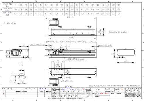
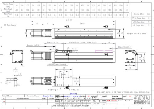
Mechanical Specifications and Dimensions
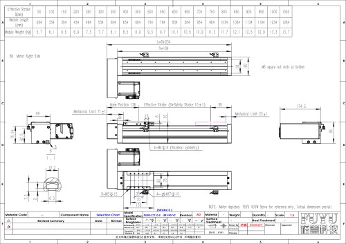
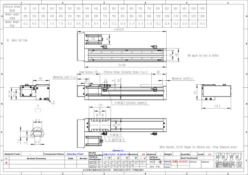
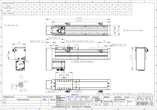
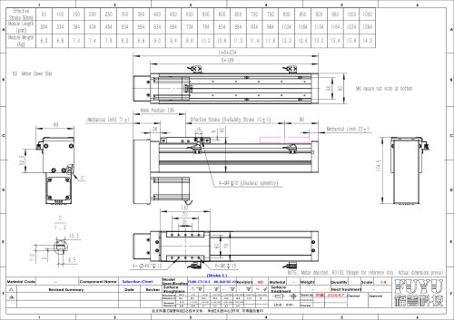
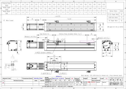
The document provides detailed mechanical dimensions and specifications for a module with bilateral symmetry, including mechanical limits, home position, and effective stroke. Key dimensions include mechanical limits at 71 and 23 units, a home position at 136 units, and an effective stroke defined as S plus a safety stroke of 10±1 mm, totaling 88 mm in one example.
Additional mechanical features include 4-M4 holes with 8 mm spacing, 4-4H7 holes at 10 mm, and 6-M5 holes at 15 mm. The module length (L) is calculated as S + 234 mm, where S is the effective stroke.
Module Stroke, Length, and Weight Data
| Effective Stroke S (mm) | Module Length L (mm) | Module Weight (Kg) |
|---|---|---|
| 50 | 284 | 5.7 |
| 100 | 334 | 6.1 |
| 150 | 384 | 6.5 |
| 200 | 434 | 6.9 |
| 250 | 484 | 7.3 |
| 300 | 534 | 7.7 |
| 350 | 584 | 8.1 |
| 400 | 634 | 8.5 |
| 450 | 684 | 8.9 |
| 500 | 734 | 9.3 |
| 550 | 784 | 9.7 |
| 600 | 834 | 10.1 |
| 650 | 884 | 10.5 |
| 700 | 934 | 10.9 |
| 750 | 984 | 11.3 |
| 800 | 1034 | 11.7 |
| 850 | 1084 | 12.1 |
| 900 | 1134 | 12.5 |
| 950 | 1184 | 12.9 |
| 1000 | 1234 | 13.3 |
| 1050 | 1284 | 13.7 |
Material, Surface, and Tolerance Specifications
The document includes references to surface roughness, surface treatment, heat treatment, and material codes, although specific details are not fully provided. Dimensional tolerances vary by size range, with values from ±0.1 mm for dimensions between 3 and 60.5 mm, up to ±2 mm for dimensions between 2000 and 4000 mm.
Geometric tolerances are also specified, ranging from 0.02 mm for dimensions between 10 and 30 mm, up to 0.4 mm for dimensions between 1000 and 3000 mm.
Additional Notes and References
- The motor shown is a FUYU 400W servo motor for reference only; actual motor dimensions may vary.
- M6 square nut slots are located at the bottom of the module.
- The model specification referenced is A0FSL80-C7L10-E-BL-F40-V2.
- The document is a technical file belonging to FUYU Technology and is restricted from unauthorized copying.
- Drawn and revised by personnel with dates and revision notes included.
Catalog excerpts
Heat Treatment Checked Approved
Open the catalog to page 1All FUYU Technology catalogs and technical brochures
 Electric Cylinder FEC
5 Pages
 Servo Cylinder Electric Actuator
21 Pages
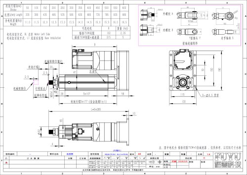 FEC60-BL
1 Page
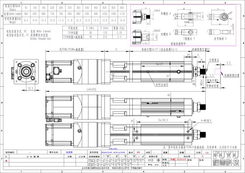 FEC60-BC
1 Page
 FSL80-BR-F40-V2
1 Page
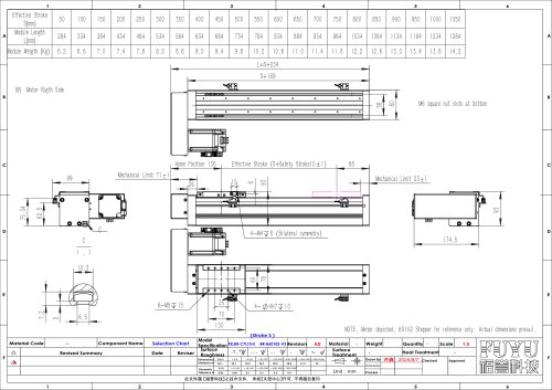 FSL80-BR-B60102-V2
1 Page
 FSL80-BL-B60102-V2
1 Page
 FSL80-BD-F40-V2
1 Page
 FSL80-BD-B60102-V2
1 Page
 FSL80-BC-F40-V2
1 Page
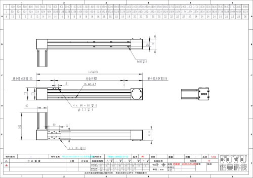
 FSL80-BC-B60102-V2
1 Page
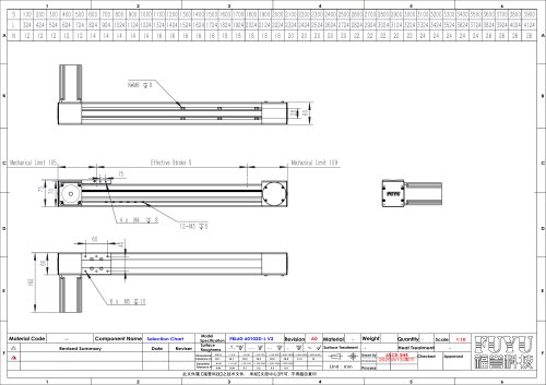
 FBL60-R-B60102D(V2)
1 Page
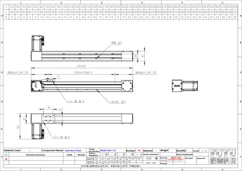
 FBL60-L-B60102D(V2)
1 Page
 FBL60-F40 V2-L
1 Page
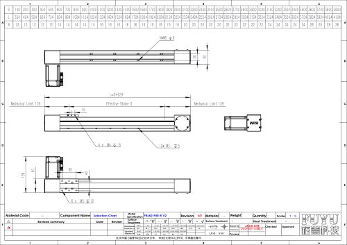 FBL60-F40 V2
1 Page
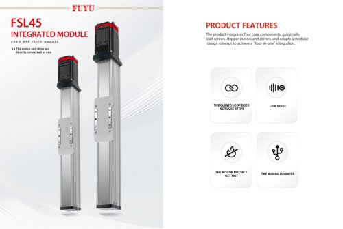 FSL45
FSL4510 Pages

Archived catalogs
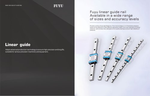 Ball Linear Guide Series
11 Pages
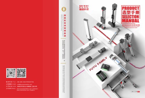 FKK&FXZ
26 Pages
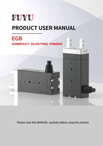 ELECTRIC GRIPPER EGB SERIES
17 Pages
 linear rail
25 Pages
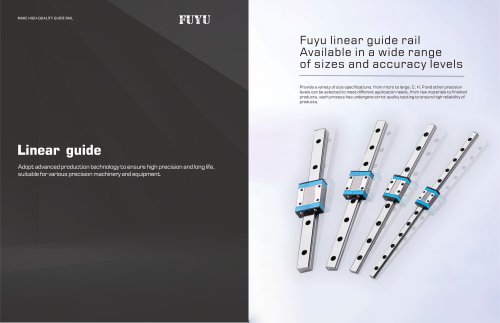 LMFN12C & LEGH15CA
11 Pages
 Belt Driven FTB Double Track
8 Pages
 Linear Module FSL Dustproof
6 Pages
 Ball Screw FTH Duoble Track
8 Pages


- Fuyu actuator
- Fuyu industrial robot
- Fuyu linear actuator
- Fuyu electric actuator
- Fuyu positioning stage
- Fuyu linear positioning stage
- Servo-motor
- Handling robot
- Fuyu motorized positioning stage
- Fuyu compact actuator
- Fuyu precision positioning stage
- Fuyu screw actuator
- High-performance servo motor
- Motor controller
- AC servo-motor
- Compact robot
- Fuyu linear guide
- High-speed robot
- Fuyu industrial actuator
- Fuyu technology positioning stage