- Company
- Products
- Catalogs
- News & Trends
- Exhibitions
TFF Series
1 /13Pages

TFF Series
1 /13Pages
Catalog excerpts

Torque Sensor Family Manual Sensor Solutions Source Load · Torque · Pressure · Multi-Axis · Calibration · Instruments · Software
Open the catalog to page 1
TFF Torque Sensor Family Manual Table of Contents Key Features. . . . . . . . . . . . . . . . . . . . . . . . . . . . . . . . . . . . . . 3 Shield Usage and Connections . . . . . . . . . . . . . . . . . . . . . 10 . . Maximum Installation Torque. . . . . . . . . . . . . . . . . . . . . . . . . 6 Cable Care and Routing. . . . . . . . . . . . . . . . . . . . . . . . . . . . . 7 Further Support Resources. . . . . . . . . . . . . . . . . . . . . . . . . . 13 Sensor Solution Source Load · Torque · Pressure · Multi-Axis · Calibration · Instruments · Software
Open the catalog to page 2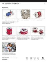
TFF Torque Sensor Family Manual The TFF (Torque Flange to Flange) sensor series measures the torque between a stationary or resistive moment or torque. Since the TFF sensor measures a static moment, it does not fully rotate with an applied torque. The TFF series features a through hole design with tapered edges, which helps to center the sensor. The through hole design allows for a shaft (or other rotating items) to pass through the sensor. The updated TFF400 has a built-in overload protection system allowing up to 300% for the 5 to 1,000 in-oz capacities, and 150% for the 100 to 500 in-lb capacities....
Open the catalog to page 3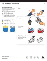
TFF Torque Sensor Family Manual Mechanical Installation The following precautions should be observed to avoid damage to the TFF sensor during installation and usage. • Store in a dry area without fixtures. Sensors with overload protection wire cut gaps, if exposed, should be regularly cleaned to maintain proper deflection path. 1. Do not pull on or carry sensor by cable. Avoid conditions that exceed the sensor’s spec sheet IP rating. 2. Monitor sensor output for effects on zero output during installation to avoid damage. Non-loading surface (cover), do not contact while loading O Active end (top...
Open the catalog to page 4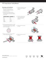
TFF Torque Sensor Family Manual Mounting and Installation • Refer to the sensor spec sheet for information on proper torque sensor orientation for best performance and to limit cable influence. 1. TFF325 and TFF350 come with dowel pin holes to help with alignment. • Measurements are called out on the sensor spec sheet and have the following tolerances based on the number of decimal points present. DECIMAL FORMAT 2. TFF325 had additional flats that can assist with fixture attachment and sensor placement. • Bolt hole placements are called out in a Bolt Circle Diameter (BCD) which is an imaginary...
Open the catalog to page 5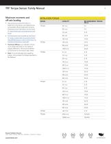
TFF Torque Sensor Family Manual Maximum moments and off-axis loading INSTALLATION TORQUE • Note: To avoid damage when applying torque, only constrain the flange attached to the fastener. RECOMMENDED TORQUE (lbf-in) • Torsional stiffness is an indication of how much torque will result in one radian of angular deflection. The torsional stiffness can be found on the sensor’s spec sheet. • An Extraneous how-to-guide can be found at: https://media.futek.com/content/futek/ files/pdf/Extraneous_Load_Factors/How_To_ Calculate_Extraneous_Loads.pdf • Use extraneous load information to determine if the...
Open the catalog to page 6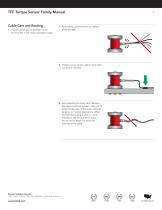
TFF Torque Sensor Family Manual Cable Care and Routing • Cable material type and length can be found online in the sensor description page. 1. Avoid stress and movement on cable to avoid damage. 2. Properly secure sensor cable to limit cable movement influence 3. Avoid bending the strain relief. Bends in the cable should not exceed a radius of 10 times the diameter of the sensor cable for dynamic, or moving, applications. When permanently routing a cable in a static installation, the minimal bend radius should not fall below 2-3 times the diameter of the cable. Sensor Solution Source Load · Torque...
Open the catalog to page 7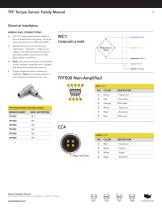
RECEPTACLE WHITE TFF Torque Sensor Family Manual The TFF torque sensor series utilizes a four-wire bare lead connection, a four-pin Lemo connection or a DB9 with TEDS. Standard A four-wire connections are DR-4S-6 RECEPTACLE +Excitation, –Excitation, +Signal, and C –Signal. The standard coloring code for the above listed connections are Red, Black, Green, and White. Bridge Sensor XXXΩ – Excitation (Black) Note: the Lemo connection is considered D a quick release connection and is slipped out rather than twisted for removal.KEY A right angle exit Lemo connector is available. Note: Connection position...
Open the catalog to page 8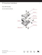
TFF Torque Sensor Family Manual Sensor DB-9 Assembly MALE DB9 CONNECTOR (SUPPLIED) DB9 Screws Bottom Cover Cover Screws Washer Covers Sensor Solution Source Load · Torque · Pressure · Multi-Axis · Calibration · Instruments · Software
Open the catalog to page 9
TFF Torque Sensor Family Manual Shield Usage and Connections • Cable shielding should be grounded on one end, either the sensor side or instrument side to avoid ground loops. • A shield connection listed as floating on a sensor’s spec sheet means the cable shield is not connected on the sensor side and may be connected on the instrument side to ground. Shield Wires • Shield connections are located on the sensor’s spec sheet. Power Supply • A yearly calibration is recommended. But verification and calibration period shall be defined based on application, conditions, endurance and usage. A shunt...
Open the catalog to page 10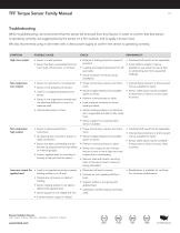
TFF Torque Sensor Family Manual Troubleshooting When troubleshooting, we recommend that the sensor be removed from any fixtures. In order to confirm that that sensor is operating correctly, we suggest placing the sensor on a firm surface, and to apply a known load. We also recommend using a volt meter with a clean power supply to confirm the sensor is operating correctly. POSSIBLE CAUSE High zero output • Sensor is under preload • Fixtures or bolting stress for causes of pre-load. • Overload shift would not be repairable. • Sensor has been overloaded from too much load, off axis load, or moment....
Open the catalog to page 11All FUTEK Advanced Sensor Technology, Inc. catalogs and technical brochures
 IHH500
4 Pages
 IPM650
3 Pages
 TDF675
2 Pages
 TDF650
2 Pages
 TDF600
2 Pages
 TDF400
2 Pages
 PFT510
2 Pages
 LTH Series
12 Pages
 LLB Series
13 Pages
 LCB Series
13 Pages
 FUTEK MODEL QTA163
1 Page
 Product Guide Eight Edition
36 Pages
 PMP410
1 Page
 PMP927
1 Page
 MBA400 series
2 Pages
 MBA500 series
2 Pages
 MTA400 series
2 Pages
 MTA500 series
2 Pages
 MTA505
2 Pages
 MTA600
2 Pages
 MAU300
1 Page
 IAC200
2 Pages
 IAA200
2 Pages
 IAA300
2 Pages
 FSH03912
2 Pages
 IHH500 Pro
4 Pages
 FSH03460
4 Pages
 FSH03633
3 Pages
 FSH03395
2 Pages
 FSH03927
2 Pages
 FSH03631
2 Pages
 USB520 series
3 Pages
 MODEL IAC200
2 Pages
 FSH00820: PFP350
1 Page
 FUTEK Product Guide
36 Pages
 Application Booklet
68 Pages
 Waste Management
1 Page
 Automated Capping Press
1 Page
 Nut Runner Force/Torque
1 Page
 Motor Test Stand
1 Page
 Power Tool Measurement
1 Page
 Torque/Motor Test Stand
1 Page
 Portable Crane Weighing
1 Page
 Material Force Testing
1 Page
 Batch Weighing
1 Page
 Snow Shoe Testing
1 Page
 Robotic Tactile Sensing
1 Page
 Nut Runner Force/Torque
1 Page
 DNA Synthesis
1 Page
 Multihead Weigher
1 Page
 Medical Patient Lift
1 Page
 Linear Test Stand
1 Page
 Silo Measurement
1 Page
 Tank Dispensing
1 Page
 Wire Tension Measurement
1 Page
 Toggle Force Clamp
1 Page
 Bolt Fastening
1 Page
 Medical Bag Weighing
1 Page


Archived catalogs
 FUTEK 2005 Catalog
24 Pages
 Product Guide 2007
24 Pages
 Medical / Rehabilitation
1 Page
 Automotive
1 Page
 Special and custom
1 Page
- Force sensor
- Analysis software solution
- Tension/compression force transducer
- Steel load cell
- Strain gauge force sensor
- Terminal box
- Digital indicator
- Stainless steel force transducer
- Pressure probe
- Wall-mounted splice box
- Panel panel meter
- Measurement software
- Signal amplifying integrated circuit
- Beam type force sensor
- Compression force transducer
- Polymer junction box
- Membrane pressure sensor
- Analog pressure sensor
- IP67 force transducer
- Test software