- Catalogs
- FUTEK Advanced Sensor Technology, Inc.
- MTA Series Multi-Axis Sensor Family Manual
- Company
- Products
- Catalogs
- News & Trends
- Exhibitions
MTA Series Multi-Axis Sensor Family Manual
1 /12Pages

MTA Series Multi-Axis Sensor Family Manual
1 /12Pages
Catalog excerpts

Multi-Axis Sensor Family Manual Sensor Solutions Source Load · Torque · Pressure · Multi-Axis · Calibration · Instruments · Software
Open the catalog to page 1
MTA Multi-Axis Sensor Family Manual Table of Contents Features . . . . . . . . . . . . . . . . . . . . . . . . . . . . . . . . . . . . . . . . 3 . . Shield Usage and Connections . . . . . . . . . . . . . . . . . . . . . . 9 . . Maximum Installation Torque. . . . . . . . . . . . . . . . . . . . . . . . . 4 Cable Care and Routing. . . . . . . . . . . . . . . . . . . . . . . . . . . . . 6 Further Support Resources. . . . . . . . . . . . . . . . . . . . . . . . . . 12 Sensor Solution Source Load · Torque · Pressure · Multi-Axis · Calibration · Instruments · Software
Open the catalog to page 2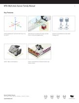
MTA Multi-Axis Sensor Family Manual Triaxial capability for moments and thrust or Fx, Fy, and Fz. Ideal solution to measure lift, drag, and side force in wind tunnel applications. Sensor Solution Source Load · Torque · Pressure · Multi Axis · Calibration · Instruments · Software Used in flight control systems. Sensor Solution Source Used in measurement of robotic Actuator and reaction forces. Load · Torque · Pressure · Multi-Axis · Calibration · Instruments · Software Solution for quantification of test stand misa
Open the catalog to page 3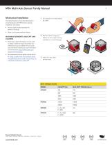
MTA Multi-Axis Sensor Family Manual Mechanical Installation The following items should be observed to avoid damage to the MTA sensor during installation and usage. 1. Do not pull on or carry sensor by cable. • Avoid conditions that exceed the sensor’s IP rating. • Store in a dry area without fixtures. MAXIMUM MOMENTS AND OFF-AXIS LOADING 2. Monitor sensor output for effects on zero output during installation to avoid damage. • Extraneous load information can be used to assist in determining if the sensor can withstand any unavoidable off-axis loads and moments. Extraneous load information can...
Open the catalog to page 4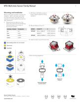
MTA Multi-Axis Sensor Family Manual Mounting and Installation Below is information for proper mounting and installation. Refer to the sensor spec sheet for thread information and proper load cell orientation to maximize performance and limit cable interference. • Measurements are called out on the sensor spec sheet and have the following tolerances based on the number of decimal points present. 1. MTA 500 and MTA505 provide pin holes to support alignment during installation. 2. Moment Reference Points ‘D’ D DECIMAL FORMAT 3. Support surfaces must be flat and inline Non-loading surface, do not...
Open the catalog to page 5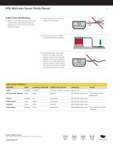
MTA Multi-Axis Sensor Family Manual Cable Care and Routing • Below is information for proper cable care and handling. Cable material type and length can be found online in the sensor description page. 1. Avoid stress and movement on cable to avoid damage. 2. Properly secure sensor cable to limit cable movement influence. 3. Avoid bending the strain relief. Bends in the cable should not exceed a radius of ten times the diameter of the sensor cable for dynamic, or moving, applications and not exceed a onetime static, permanent, bend of two to three times the diameter of the cable. CABLE JACKET...
Open the catalog to page 6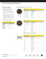
Electrical Installation 1 2 4 5 • Wire connetions are + Excitation, 3 – Excitation, + Signal, and – Signal. The coloring code for the MTA series connections are Red, Black, Green, andRED White. E C BLACK D ALIGN WITH KEY Sensor Receptacle View • Consult the sensor’s online spec sheet for any further wiring information. • Sense wires connect internally to excitation WHITE points and can be used to monitor voltage supply drops. When not utilized 1 2 3 4 5 6 for monitoring voltage supply drops, pair BLACK ± Sense with corresponding ± Excitation connections. DP-4S-1 MATING – Signal CONNECTOR BACK...
Open the catalog to page 7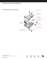
MTA Multi-Axis Sensor Family Manual Sensor Male DB Connector Assembly DB9 Screws Bottom Cover Cover Screws Washer Covers Sensor Solution Source Load · Torque · Pressure · Multi-Axis · Calibration · Instruments · Software
Open the catalog to page 8
MTA Multi-Axis Sensor Family Manual Shield Usage and Connections • Cable shielding should be grounded on one end, either the sensor side or instrument side to avoid ground loops. Jacket Shield • A shield connection listed as floating on a sensors spec sheet means the cable shield is not connected on the sensor side and may be connected on the instrument side to ground. Power Supply • A yearly calibration is recommended. But verification and calibration period shall be defined based on application, conditions, endurance and usage. A shunt is an external resistance applied across two points on...
Open the catalog to page 9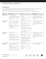
MTA Multi-Axis Sensor Family Manual Troubleshooting When troubleshooting, we recommend that the sensor be removed from any fixtures. In order to confirm that that sensor is operating correctly, we suggest placing the sensor on a firm surface, and to apply a known load. We also recommend using a volt meter with a clean power supply to confirm the sensor is operating correctly. POSSIBLE CAUSE High zero output • Sensor is under preload • Fixtures or bolting stress for causes of pre-load. • Overload shift would not be repairable. • Sensor has been overloaded from too much load, off axis load, or...
Open the catalog to page 10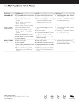
MTA Multi-Axis Sensor Family Manual POSSIBLE CAUSE Zero output drift • Unstable power supply, or noisy power supply, to sensor. • Stability of power supply and noise levels. • Internal damage from liquid exposure is not repairable. • Sensor exposed to temperature change. • For temperature changes or unevenly distributed temperature changes. • Recalibration is available for confirmation of sensor performance. • Sensor exposed to pre-load from fixture or mounting. • Possible loose fixtures and bolts • Sensor exposed to liquid or humidity. Creep in output while under load • Load or fixtures are...
Open the catalog to page 11All FUTEK Advanced Sensor Technology, Inc. catalogs and technical brochures
 IHH500
4 Pages
 IPM650
3 Pages
 TDF675
2 Pages
 TDF650
2 Pages
 TDF600
2 Pages
 TDF400
2 Pages
 PFT510
2 Pages
 LTH Series
12 Pages
 TFF Series
13 Pages
 LLB Series
13 Pages
 LCB Series
13 Pages
 FUTEK MODEL QTA163
1 Page
 Product Guide Eight Edition
36 Pages
 PMP410
1 Page
 PMP927
1 Page
 MBA400 series
2 Pages
 MBA500 series
2 Pages
 MTA400 series
2 Pages
 MTA500 series
2 Pages
 MTA505
2 Pages
 MTA600
2 Pages
 MAU300
1 Page
 IAC200
2 Pages
 IAA200
2 Pages
 IAA300
2 Pages
 FSH03912
2 Pages
 IHH500 Pro
4 Pages
 FSH03460
4 Pages
 FSH03633
3 Pages
 FSH03395
2 Pages
 FSH03927
2 Pages
 FSH03631
2 Pages
 USB520 series
3 Pages
 MODEL IAC200
2 Pages
 FSH00820: PFP350
1 Page
 FUTEK Product Guide
36 Pages
 Application Booklet
68 Pages
 Waste Management
1 Page
 Automated Capping Press
1 Page
 Nut Runner Force/Torque
1 Page
 Motor Test Stand
1 Page
 Power Tool Measurement
1 Page
 Torque/Motor Test Stand
1 Page
 Portable Crane Weighing
1 Page
 Material Force Testing
1 Page
 Batch Weighing
1 Page
 Snow Shoe Testing
1 Page
 Robotic Tactile Sensing
1 Page
 Nut Runner Force/Torque
1 Page
 DNA Synthesis
1 Page
 Multihead Weigher
1 Page
 Medical Patient Lift
1 Page
 Linear Test Stand
1 Page
 Silo Measurement
1 Page
 Tank Dispensing
1 Page
 Wire Tension Measurement
1 Page
 Toggle Force Clamp
1 Page
 Bolt Fastening
1 Page
 Medical Bag Weighing
1 Page


Archived catalogs
 FUTEK 2005 Catalog
24 Pages
 Product Guide 2007
24 Pages
 Medical / Rehabilitation
1 Page
 Automotive
1 Page
 Special and custom
1 Page
- Analysis software solution
- Tension/compression force transducer
- Steel load cell
- Terminal box
- Strain gauge force sensor
- Digital indicator
- Stainless steel force transducer
- Pressure probe
- Wall-mounted splice box
- Panel panel meter
- Measurement software
- Signal amplifying integrated circuit
- Beam type force sensor
- Compression force transducer
- Polymer junction box
- Membrane pressure sensor
- Analog pressure sensor
- IP67 force transducer
- Test software