- Company
- Products
- Catalogs
- News & Trends
- Exhibitions
IPM650
1 /3Pages

IPM650
1 /3Pages
Catalog excerpts

Panel Mount Display SPECIFICATIONS GENERAL 21k point data logging Bridge resistance measurement Keypad options (Track/Hold - Peak/Valley Reset - Unit - Tare/Gross-Shunt - Channel Display-Menu) First peak/first valley feature User friendly navigation menu Shunt calibration Universal unit conversion 14 Sensor profile storage Supports 1451.4 standard (TEDS template 30 and 33) Powers on when plugged in (QSH01633 Version) IMPORTANT NOTE: ONLY CONNECT DEVICE TO USB 2.0 PORT Data Logging Profile Storage Sampling Rate Internal Resolution Resolution (Noise Free) Integrated Digital Filter Operating Temperature Storage Temperature Internal Shunt Resistance Value Readout Nonlinearity Front Panel IP Rating STRAIN GAUGE mV/V INPUT Bridge Excitation Standard Input Range Optional Input Range Reading Error** VOLTAGE INPUT Standard Input Range Reading Error** CURRENT INPUT Standard Input Range OUTPUT Analog Voltage Minimum Load Impedance (Voltage) Analog Current Maximum Load Impedance (Current) 2 Individual Relay Outputs External Supply Output Digital Packetized Data ASCII Output Update Rate POWER ADAPTER Input Input Current CONFORMITY RoHS * Refer to IHH500 User Manual for conditions on analog output bandwidth. ** When no system calibration is performed. Sensor Solution Source Load · Torque · Pressure · Multi-Axis · Calib
Open the catalog to page 1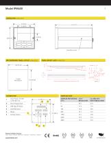
Panel Mount Jack Panel Mount Jack RECOMMENDED PANEL CUTOUT inches [mm] PANEL MOUNT JACK inches [mm] 0.17 2X 0.092 Set Screw, #6-32-3/8” Long, Alloy Steel (Zinc-Plated) Maximum recommended wall thickness for panel mount is 3/8” SAMPLING RATE SAMPLES PER SECOND (SPS) Strain Gauge Input Amplified Input Analog Output Sensor Solution Source Load · Torque · Pressure · Multi-Axis · Calibration · Instruments · Software
Open the catalog to page 2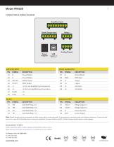
CONNECTORS & WIRING DIAGRAM IPM650 Strain Gauge Input B1 Channel Enter Display Back Exit Shunt Power Adapter Analog Output Compatible with USB 2.0 only AMPLIFIED INPUT STRAIN GAUGE INPUT TEDS Data –V and –mA Amplified Input Connections +V and +mA Amplified Input Connections ANALOG OUTPUT Solid State Relay 2 (–) Voltage Output (–) Solid State Relay 2 (+) Solid State Relay 1 (–) Ground (current) Solid State Relay 1 (+) Current Output Note: Shield should only be connected on either sensor side or instrument side. If connected on instrument side use following directions. Connect shield to pin A1...
Open the catalog to page 3All FUTEK Advanced Sensor Technology, Inc. catalogs and technical brochures
 IHH500
4 Pages
 TDF675
2 Pages
 TDF650
2 Pages
 TDF600
2 Pages
 TDF400
2 Pages
 PFT510
2 Pages
 LTH Series
12 Pages
 TFF Series
13 Pages
 LLB Series
13 Pages
 LCB Series
13 Pages
 FUTEK MODEL QTA163
1 Page
 Product Guide Eight Edition
36 Pages
 PMP410
1 Page
 PMP927
1 Page
 MBA400 series
2 Pages
 MBA500 series
2 Pages
 MTA400 series
2 Pages
 MTA500 series
2 Pages
 MTA505
2 Pages
 MTA600
2 Pages
 MAU300
1 Page
 IAC200
2 Pages
 IAA200
2 Pages
 IAA300
2 Pages
 FSH03912
2 Pages
 IHH500 Pro
4 Pages
 FSH03460
4 Pages
 FSH03633
3 Pages
 FSH03395
2 Pages
 FSH03927
2 Pages
 FSH03631
2 Pages
 USB520 series
3 Pages
 MODEL IAC200
2 Pages
 FSH00820: PFP350
1 Page
 FUTEK Product Guide
36 Pages
 Application Booklet
68 Pages
 Waste Management
1 Page
 Automated Capping Press
1 Page
 Nut Runner Force/Torque
1 Page
 Motor Test Stand
1 Page
 Power Tool Measurement
1 Page
 Torque/Motor Test Stand
1 Page
 Portable Crane Weighing
1 Page
 Material Force Testing
1 Page
 Batch Weighing
1 Page
 Snow Shoe Testing
1 Page
 Robotic Tactile Sensing
1 Page
 Nut Runner Force/Torque
1 Page
 DNA Synthesis
1 Page
 Multihead Weigher
1 Page
 Medical Patient Lift
1 Page
 Linear Test Stand
1 Page
 Silo Measurement
1 Page
 Tank Dispensing
1 Page
 Wire Tension Measurement
1 Page
 Toggle Force Clamp
1 Page
 Bolt Fastening
1 Page
 Medical Bag Weighing
1 Page


Archived catalogs
 FUTEK 2005 Catalog
24 Pages
 Product Guide 2007
24 Pages
 Medical / Rehabilitation
1 Page
 Automotive
1 Page
 Special and custom
1 Page
- Force sensor
- Analysis software solution
- Tension/compression force transducer
- Steel load cell
- Strain gauge force sensor
- Terminal box
- Digital indicator
- Stainless steel force transducer
- Pressure probe
- Measurement software
- Panel panel meter
- Signal amplifying integrated circuit
- Beam type force sensor
- Wall-mounted splice box
- Compression force transducer
- Analog pressure sensor
- Membrane pressure sensor
- Polymer junction box
- IP67 force transducer
- Test software