- Catalogs
- FUJI ELECTRIC France
- Datasheet temperature controller PUM-A-B
Datasheet temperature controller PUM-A-B
1 /8Pages
Datasheet temperature controller PUM-A-B
1 /8Pages
Catalog excerpts
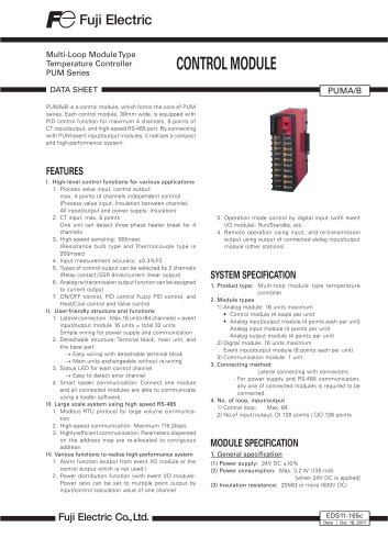
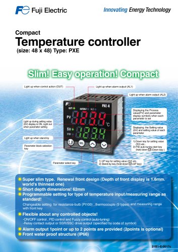
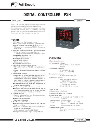
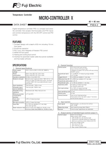
Multi-Loop Module Type Temperature Controller PUM Series DATA SHEET PUMA/B is a control module, which forms the core of PUM series. Each control module, 30mm wide, is equipped with PID control function for maximum 4 channels, 8 points of CT input/output, and high-speed RS-485 port. By connecting with PUM event input/output modules, it realizes a compact and high-performance system. 1. Process value input, control output: max. 4 points (4 channels independent control) (Process value input: Insulation between channlel, All input/output and power supply: Insulation) One unit can detect three phase heater break for 4 channels (Resistance bulb type and Thermocouqle type is 200msec) 4. Input measurement accuracy: ±0.3%FS 5. Types of control output can be selected by 2 channels (Relay contact/SSR drive/current linear output) 6. Analog re-transmission output function can be assigned to current output 7 ON/OFF control, PID control Fuzzy PID control, and Heat/Cool control and Valve control II. User-friendly structure and functions 1. Lateral connection : Max.16 units (64 channels) + event input/output module 16 units = total 32 units Simple wiring for power supply and communication 2. Detachable structure: Terminal block, main unit, and the base part ^ Easy wiring with detachable terminal blcok ^ Main units exchangeable without re-wiring 3. Status LED for each control channel ^ Easy to detect error channel 4. Smart loader communication: Connect one module and all connected modules are able to communicate using a loader software. III. Large scale system using high speed RS-485 1. Modbus RTU protocol for large volume communication 2. High-speed communication: Maximum 115.2kbps 3. Highly-efficient communication: Parameters dispersed on the address map are re-allocated to contiguous address IV. Various functions to realize high-performance system 1. Alarm function (output from event I/O module or the control output which is not used ) 2. Power distribution function (with event I/O module): Power ratio can be set to multiple point output by input/control calculation value of one channel 3. Operation mode control by digital input (with event I/O module): Run/Standby, etc. 4. Remote operation using input, and re-transmission output using output of connected alalog input/output module (other stations) 1. Product type: Multi-loop module type temperature 2. Module types 1) Analog module: 16 units maximum • Control module (4 loops per unit) • Analog input/output module (4 points each per unit) Analog input module (4 points per unit) Analog output module (4 points per unit) 2) Digital module: 16 units maximum Event input/output module (8 points each per unit) 3) Communication module: 1 unit 3. Connecting method: Lateral connecting with connectors - For power supply and RS-485 communication, any one of connected modules is required to be connected. 4. No. of loop, input/output 1) Control loop: Max. 64 2) No.of input/output: DI 128 points / DO 128 points (3) Insulation resistance: 20MW or more (500V DC)
Open the catalog to page 1
- Electric life: - Load resistance: Resolution: Ripple current: Load resistance: Insulation: Power supply o all terminals 1000V AC 1 min Relay contact o all terminals 2.1 Process value input (1) No. of input: 2 or 4 points (1 point/channel) (2) Input setting: Input code selection (3) Input signal: See table 1 Select from group I or II depending on the model code. (setting can be done by channel within group) [Group I] a) Thermocouple b) Resistance bulb (3 wire) [Group II] c) DC voltage, current (4) Measurement range and input type: See table 1 b) Resistance bulb input: ±0.3%FS ±1 digit or ±1°C...
Open the catalog to page 2
3.2 Analog re-transmission output (1) No. of output: 2 points (OUT3, OUT4 applied) (2) Output type: Current output (4 to 20mA DC,0 to 20mA (3) Option: Output scaling (1) Communication standards: RS-485 compatible (3) Communication, synchro method: Two-wire, half-duplex, asynchronous cycle (5) Communication distance: 1km (38.4kbps or less), (6) Recommended cable: KPEV-SB 0.5sq-equivalent 33 units (master and slave) (32 units if any modules other than PUM series are included in slaves.) (8) Data format: Data bit; 8, parity; even / odd / none (9) Protocol: Modbus RTU compatible (10) Insulation:...
Open the catalog to page 3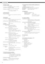
(1) Impact of power outage: Outage of 2ms or less ; no impact (2) Operation after power outage: Start from the first step (cold start) Nonvolatile memory (EEPROM) Diagnosis method: Program error monitoring by watch dog timer DIN rail mounting or mounting with M3 screws inside a cabinet (excluding terminal cover and projected part) - Process value input/control output: Detachable terminal block (M3 screw x 20 terminals) - Power supply connection: Terminal block on the base part (M3 screw x 2 terminals) Power is supplied via side connectors in case of lateral connecting. (Max. 33 units) Terminal...
Open the catalog to page 4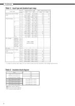
* In case of currenet input, attach I/V unit which comes with the controller to the voltage input terminal [table 2] Insulation block diagram Power Basic insulation (1500V AC) Functional insulation (1000V AC) - Functional insulation (500V AC)
Open the catalog to page 6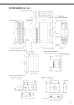
OUTLINE DIAGRAM (Unit : mm) Front terminal cover (Option) Base part (Main unit is detached) Terminal block (at attach/detach) Hole for screw mounting Hole for screw mounting Main unit (at attach/detach) Dimensions for screw mounting Notice at the installation Please keep the distance of 30mm from this instrument to radiate. [50mm is recommended] Heater current detector (CT) Specification : 1 to 30 A Type : CTL-6-S-H
Open the catalog to page 7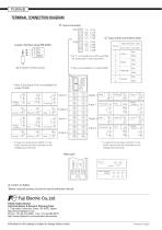
Terminal connection diagram CT input connector CN1 Loader interface plug (RS-232C) CT input cable connection table Cable distinction color Pin No. Cover color * No. 2, 4, 6 and 8 pins of CN1 and CN2 are connected in the instruments. * CN2 is not available for model PUMB. * Input 3 and Input 4 are not available for model PUMB. * In case of current input, attach I / V unit which comes with the controller to the voltage input terminal. Voltage/ Current* Voltage/ Current* Voltage/ Current* * In case of current input, attach I / V unit which comes with the controller to the voltage input terminal....
Open the catalog to page 8All FUJI ELECTRIC France catalogs and technical brochures
 Temperature controller PXE
2 Pages
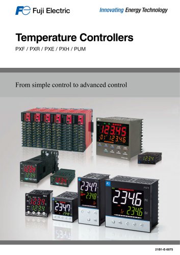 Temperature controllers
24 Pages
 HMI Technoshot TS1000 series
7 Pages
 HMI Technoshot TS2000 serie
2 Pages
 HMI Monitouch X1 series
14 Pages
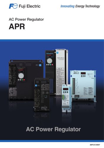 Power controller - APR series
56 Pages
 Gas analysers
21 Pages
 CROSS STACK LASER GAS ANALYZER
12 Pages
 ZKM Oxygen Gas Analyzers
8 Pages
 ZPAF Biogas analyser
4 Pages


- Fuji Electric flow meter
- Display module
- Temperature probe
- Fuji Electric volume flow meter
- Fuji Electric liquid flow meter
- Fuji Electric gas analyzer
- Automation software solution
- Fuji Electric concentration analyzer
- Fuji Electric monitoring analyzer
- Industrial display panel
- Resistance temperature sensor
- Analysis software solution
- Fuji Electric pressure transmitter
- Process software
- Real-time software
- Fuji Electric analog pressure transmitter
- Fuji Electric waterproof flow meter
- Control software
- Fuji Electric gas flow meter
- Level probe