- Catalogs
- FUJI ELECTRIC France
- Datasheet temperature controller PSC200
Datasheet temperature controller PSC200
1 /12Pages
Datasheet temperature controller PSC200
1 /12Pages
Catalog excerpts

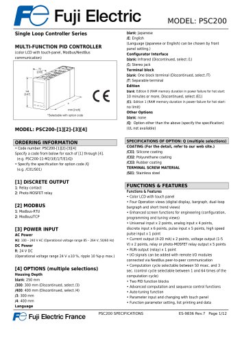
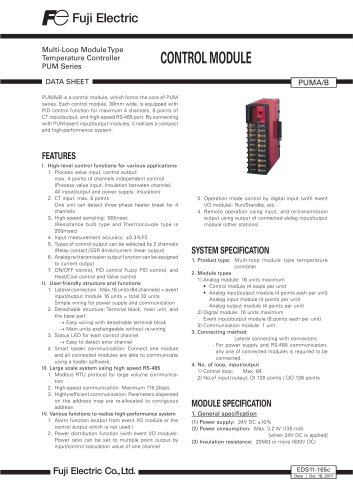
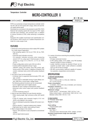
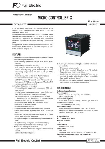
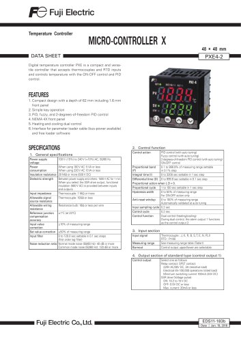
MODEL: PSC200Single Loop Controller Series MULTI-FUNCTION PID CONTROLLER (color LCD with touch-panel, Modbus/NestBus communication) MODEL: PSC200-[1][2]-[3][4] blank: Japanese /E: English (Language (Japanese or English) can be chosen by front panel setting.) Configurator Interface blank: Infrared (Discontinued, select /1) Terminal block blank: One block terminal (Discontinued, select /T) blank: Edition 0 (RAM memory duration in power failure for hot start: 10 minutes or more, Discontinued, select /E1) /E1: Edition 1 (RAM memory duration in power failure for hot start: no limit) Other Options blank: none /Q: Option other than the above (specify the specification) (UL not available) ORDERING INFORMATION_ • Code number: PSC200-[1][2]-[3][4] Specify a code from below for each of [1] through [4]. (e.g. PSC200-11-M2/3/E/1/T/E1/Q) • Specify the specification for option code /Q (e.g. /C01/S01) SPECIFICATIONS OF OPTION: Q (multiple selections) COATING (For the detail, refer to our web site.) /C01: Silicone coating /C02: Polyurethane coating /C03: Rubber coating TERMINAL SCREW MATERIAL 1: Relay contact 2: Photo MOSFET relay M2: 100 - 240 V AC (Operational voltage range 85 - 264 V, 50/60 Hz) (Operational voltage range 24 V ±10 %, ripple 10 %p-p max.) Housing Depth Functions & Features • Color LCD with touch panel • Four Operation views (digital display, bargraph, dual-loop bargraph and short trend views) • Enhanced screen functions for engineering (configuration, programming and tuning views) • Universal input x 2 points, analog input x 4 points, discrete input x 6 points, pulse input x 5 points, high speed pulse input x 1 point • Current output (4-20 mA) x 2 points, voltage output (1-5 V) x 2 points, relay or photo-MOSFET relay output x 5 points • RUN output (relay) x 1 point • I/O signals can be added with remote I/O modules connected via NestBus peer-to-peer communication • Computation cycle selectable between 50 msec. and 3 sec. (control cycle selectable between 1 and 64 times of the computation cycle) • Advanced computation and sequence control functions • Auto-tuning function • Parameter input and changing with touch panel • Function parameter setting, list printing and data PQ Fuji Electric France PSC200 SPECIFICATIONS ES-9836 Rev.7 Page
Open the catalog to page 1
MODEL: PSC200 downloading/uploading available with Loop Configuration Builder Software (model: PSFEW) • Short trend export (CSV), display parameter setting, saving and transfer with PC Configurator Software (model: PSCCFG) • Control and supervision by SCADA software via Modbus TCP/IP or RTU communication • Selectable housing depth for ease of using existing wires in replacement: 250 mm, 300 mm and 400 mm • Separable terminal block Typical Applications • Replacement of conventional controllers • Panel operation for small-scale instrumentation RELATED PRODUCTS_ • PC Configurator cable (model: COP-US)...
Open the catalog to page 2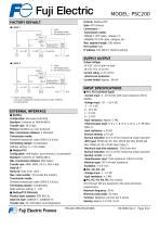
MODEL: PSC200 FACTORY DEFAULT ■ LOOP 1 P : 100% I : No integral action D : No derivative action Protocol: Modbus/TCP Data: RTU (binary) Connections: 2 Transmission media: 10BASE-T (STP cable, category 5) 100BASE-TX (STP cable, category 5e) Max. segment length: 100 meters Port number: 502 IP address: 192.168.0.1 (factory setting) SUPPLY OUTPUT ■ LOOP 2 P : 100% I : No integral action D : No derivative action Output voltage: 24 V DC ±10 % with no load 18 V DC min. at 20 mA Current rating: ≤ 22 mA DC ∙Shortcircuit protection Current limited: Approx. 30 mA *1. Factory default setting Use Loop Configuration...
Open the catalog to page 3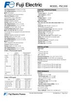
MODEL: PSC200 ON voltage/resistance: < 2.25 V, < 1.5 kQ OFF voltage/resistance: > 11.25 V > 15 kQ (Di6 is assigned to the same terminal.) Maximum frequency: 10 kHz (Computation cycle: < 500 msec.) Minimum pulse width: 0.05 msec. Common: Negative common Sensing: Approx. 12 V DC, 12 mA ON voltage/resistance: < 2 V, < 1.5 kQ OFF voltage/resistance: > 11 V, > 15 kQ Excitation: 12 V DC ±10%, 15 mA Current limiting circuit: Approx. 30 mA (Pi1 through Pi5 are assigned to the same terminals respectively.) Common: Negative common per 5 points Sensing: Approx. 12 V DC, 6 mA ON voltage/resistance: < 2.25...
Open the catalog to page 4
MODEL: PSC200 DC input: ±0.015 %/°C (±0.008 %/°F) Thermocouple input: ±0.015 %/°C (±0.008 %/°F) RTD input: ±0.015 %/°C (±0.008 %/°F) Potentiometer input: ±0.015 %/°C (±0.008 %/°F) DC output: ±0.015 %/°C (±0.008 %/°F) Precision resistor module (REM4): ±0.015 %/°C (±0.008 %/°F) Line voltage effect: ±0.1 % over voltage range Calendar clock accuracy: Monthly deviation 3 minutes at 25°C Insulation resistance: ≥ 100 MΩ with 500 V DC Dielectric strength: 1500 V AC @ 1 minute (Pv1 or supply output to Pv2 or Ai1 or Ai2 or Ai3 or Ai4 to Di1 or Di2 or Di3 or Di4 or Di5 or Pi1 or Pi2 or Pi3 or Pi4 or Pi5...
Open the catalog to page 5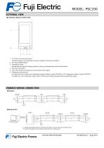
MODEL: PSC200 EXTERNAL VIEW ■ CONTROL MODULE FRONT VIEW 1. TFT Color LCD with touch panel Provides operation and engineering views to facilitate monitoring and setting 2. MV value (DOWN) button 3. Acceleration button (Accelerates MV signal’s changing speed by pressing simultaneously with MV value button) 4. MV value (UP) button 5. Auto / Man selector (changes the control mode for MV output) 6. Configurator jack and cap Connects with a PC where Loop Configuration Builder Software (model: PSFEW) or PC configurator software (model: PSCCFG) is installed via a PC configurator cable (model: COP-US)...
Open the catalog to page 6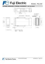
MODEL: PSC200EXTERNAL DIMENSIONS & TERMINAL ASSIGNMENTS unit: mm [inch] PQ Fuji Electric France PSC200 SPECIFICATIONS ES-9836 Rev.7 Page 7/12
Open the catalog to page 7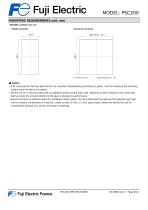
MODEL: PSC200MOUNTING REQUIREMENTS unit: mm_ ■ PANEL CUTOUT unit: mm • Single mounting • Clustered mounting Panel thickness 2.3 - 20 ■ Caution • IP55 is ensured for the front panel of the unit mounted independently according to a panel. Test the sealing at the mounting surface once the device is installed. • Set the unit on a vertical surface with its operation buttons at the lower side. Mounting in other directions may cause heat built up inside the unit and shorten its life span or degrade its performance. • Ensure that there is sufficient space for ventilation inside a panel. Do not install...
Open the catalog to page 8All FUJI ELECTRIC France catalogs and technical brochures
 Temperature controller PXE
2 Pages
 Temperature controllers
24 Pages
 HMI Technoshot TS1000 series
7 Pages
 HMI Technoshot TS2000 serie
2 Pages
 HMI Monitouch X1 series
14 Pages
 Power controller - APR series
56 Pages
 Gas analysers
21 Pages
 CROSS STACK LASER GAS ANALYZER
12 Pages
 ZKM Oxygen Gas Analyzers
8 Pages
 ZPAF Biogas analyser
4 Pages


- Fuji Electric flow meter
- Temperature probe
- Fuji Electric volume flow meter
- Fuji Electric liquid flow meter
- Fuji Electric gas analyzer
- Automation software solution
- Fuji Electric concentration analyzer
- Fuji Electric monitoring analyzer
- Industrial display panel
- Resistance temperature sensor
- Analysis software solution
- Fuji Electric pressure transmitter
- Process software
- Real-time software
- Fuji Electric analog pressure transmitter
- Fuji Electric waterproof flow meter
- Fuji Electric gas flow meter
- Control software
- Level probe