- Catalogs
- FUJI ELECTRIC France
- CROSS STACK LASER GAS ANALYZER
CROSS STACK LASER GAS ANALYZER
1 /12Pages

CROSS STACK LASER GAS ANALYZER
1 /12Pages
Catalog excerpts

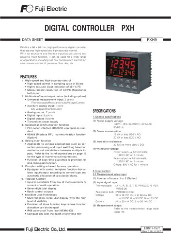
CROSS STACK LASER GAS ANALyZER (Dual beam version) DATA SHEET Cross stack laser gas analyzer (ZSS) provides continuous measurement of CO and O2 contained in flue gas in various plants. Because ZSS is installed directly on the stack or the pipe through which the target gas passes, sample gas conditioning is not required. Being highly tolerant to dust, ZSS can be installed on the upstream of a bug filter where the gas sampling is usually difficult. ZSS is the first laser gas analyzer in Japan that is designed for environmental monitoring and process monitoring. 1. Double-beam laser for two component analysis of CO and O2 2. Low maintenance 3. Low operating-cost: with no gas-sampling device and few parts to be replaced 4. Superior long-term stability 5. Fast response speed within 4 seconds—suited to combustible gas monitoring and control in converter furnaces 6. Tolerant to high temperature and high dust 7. Environment friendly: 80 VA, low power consumption 8. Analog output for transmittance is available 9. Compliant with RoHS directive (2011/65/EU) Control unit Receiver unit Transmitter unit Table 1. Measurable component, Measurable range No. of components CO+O2 (Instrument air purge) 2-laser 2-component analyzer Note 1) The minimum and maximum measuring range in the above table are for measuring path length (stack length) of 1m. See below on the ranges for other path lengths. Calculation method of measuring range for optical path length other than 1m Measuring range = [Min. or Max. range ÷ path length] Example 1) CO analyzer, path length 5m Max. range: 2 vol% ÷ 5m = 4,000ppm Min. range: 200ppm ÷ 5m = 40ppm Therefore, measuring range is between 0 to 40 ···4,000ppm Example 2) CO analyzer, path length 0.5m Max. range: 2 vol% ÷ 0.5m = 4 vol% Min. range: 200ppm ÷ 0.5m = 400ppm Therefore, measuring range is between 0 to 400ppm ···4 vol%
Open the catalog to page 1
ZSS-D Measurement principle: Non-dispersive infrared (NDIR) Measuring method: Cross-stack system (path system) Application: Waste incineration plant, industrial waste disposal facility, power plant iron and steel plant, paper plant, pulp mill, chemical plant and bioplant, etc. Light source: Near-infrared laser Laser class: Class 1 (High temperature version and instrument air purge version fall under CLASS 3B) Dimensions: Refer to outline diagram Weight (excluding cables): Receiver unit and transmitter unit: Approx. 10 kg Control unit: Approx. 8 kg Structure: Outdoor use, dustproof and rainproof...
Open the catalog to page 2
DIGITAL INPUT (OPTION) Average value reset signal: Output of converted average value is started from the initial state by applying rectangular-wave voltage (with a minimum pulse width of two seconds) to the input terminal of average value resetting. Output is reset by inputting and restarted by opening. Switchover between instantaneous value and moving average value: Switching to and from the instantaneous value and the average value of the analog output is performed by applying rectangular-wave voltage (with a minimum pulse width of two seconds) to the input terminal for switching between the...
Open the catalog to page 3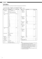
CODE SYMBOLS When ordering, be sure to submit the order sheet on the last page of this Data Sheet. 4 ZSS Digit 4 Measurable components Specification Note Code ppm CO + O2 (Air purge) V U ppm CO + O2 (High temperature) S vol% CO + O2 5 Unit ppm (1st comp), vol% (2nd comp) 7 vol% (1st comp), vol% (2nd comp) 9 6 Measuring range 0 to 2 Note 1 K (CO) 0 to 2.5 Q 0 to 4 S 0 to 5 L 0 to 10 V 0 to 15 0 0 to 20 1 0 to 25 T 0 to 50 A 0 to 100 B 0 to 200 C 0 to 250 D 0 to 400 J 0 to 500 E 0 to 1000 F 0 to 2000 G 0 to 5000 H 0 to 6000 M Others X 7 Measuring range 0 to 5 Note 1 L 0 to 10 V (O2) 0 to 15 0 0...
Open the catalog to page 4
COMBINATIONS OF MEASURABLE COMPONENTS AND RANGES Component CO+O2 (Instrument air purge) 1st comp.: CO 2nd comp.: O2 1st comp.: CO 2st comp.: O2 1st comp.: CO 2st comp.: O2 CO+O2 (High temp.) CO+O2 (vol%CO+ O2) Basic principle ZSS uses the near-infrared semiconductor laser as the light source, and photo-diode as photodetector. Each gas component has its own wavelength range where it absorbs the light, and a wavelength range consists of a set of many absorption lines, as shown in the figures below. As ZSS can aim at only one absorption-line among them, the measurement principally receives no interference...
Open the catalog to page 5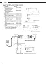
Parts name Quantity Type Cable between receiver unit and 1 ZZP*ZSSTQ404686C2 control unit (for calibration) Cable between receiver unit and 1 ZZP*ZSSTQ404685C3 transmitter unit (for calibration) Calibration gas cell (*3) 1 ZZP*ZSSTQ404736C1 (CO+O2) Optical axis adjusting tool (laser 1 ZZP*ZSSTQ404743C1 pointer, target) Check cell 1 ZZP*ZSSTQ404742C1 Filter regulator 1 ZZP*ZSSTQ505311P1 Mist separator 1 ZZP*ZSSTQ505310P1 R1/4 cap nut (plug) for mist separa1 ZZP*ZSSR850N000075 tor Flow meter (20 to 100L/min) (*4) 1 ZZP*ZSSTQ505309P1 Flow meter (4 to 50L/min) (*4) 1 ZZP*ZSSTQ505309P2 Flow meter...
Open the catalog to page 6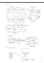
Mist separator Filter regulator Pipe with external diameter ø10 (out of supply) Flow meter measuring instrument air inlet Receiver purge outlet Drain outlet (ø10 piping) Transmitter purge outlet (8) R1/4 cap nut 420 500 Piping system diagram Receiver purge outlet Transmitter purge outlet Rc1/4 Drain outlet Piping retainer for ø10 (11) Air purge mechanical part total 20m 1m Piping material: ø10/8 Teflon pipe for ø10/8 tube (metallic tube recommendable) to Transmitter purge inlet to Receiver purge inlet to Receiver purge inlet Mist separator Filter regulator Measuring instrument air inlet (Coupling...
Open the catalog to page 7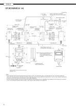
OUTLINE DIAGRAM (Unit : mm) Or air-set box 2-Flowmeter (option) Copper or SUS pipe (not supplied) Instrumentation air line joint (not supplied) Filter regulator (option) ø10/8 Teflon pipe (not supplied) Instrumentation air inlet Mist separator (option) Approx. 400 Flange of angle adjustment Purging gas inlet Receiver box (with bell-and-spigot (120×180×100) joint for ø10/8) 150 to 200 With bolt and nut (M16×55) Flange pipe to mount stack (not suppried) Approx. 432 Flange of angle adjustment Transmitter unit Cable between receiver unit and transmitter unit (standard : 2m) Note 1: Be sure to set...
Open the catalog to page 8All FUJI ELECTRIC France catalogs and technical brochures
 Temperature controller PXE
2 Pages
 Temperature controllers
24 Pages
 HMI Technoshot TS1000 series
7 Pages
 HMI Technoshot TS2000 serie
2 Pages
 HMI Monitouch X1 series
14 Pages
 Power controller - APR series
56 Pages
 Gas analysers
21 Pages
 ZKM Oxygen Gas Analyzers
8 Pages
 ZPAF Biogas analyser
4 Pages


- Display module
- Temperature probe
- Fuji Electric volume flow meter
- Fuji Electric liquid flow meter
- Automation software solution
- Fuji Electric concentration analyzer
- Industrial display panel
- Fuji Electric monitoring analyzer
- Resistance temperature sensor
- Fuji Electric pressure transmitter
- Analysis software solution
- Process software
- Real-time software
- Fuji Electric waterproof flow meter
- Fuji Electric analog pressure transmitter
- Control software
- Fuji Electric gas flow meter
- Level probe