- Catalogs
- FTI Forming Technologies Incorporated
- DYNAVISTA Shaper
DYNAVISTA Shaper
1 /65Pages

DYNAVISTA Shaper
1 /65Pages
Catalog excerpts

V9.6 Dieface Design Formability Shaper March, 2010 UNIADEX, Ltd. All Rights Reserved, Copyright(C) 2009 Nihon Unisys, Ltd.
Open the catalog to page 1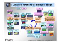
Dynavista functions for die layout design Die face Die face Twist Twist deformation deformation Shaper Shaper Hole filling Hole filling Bead Bead Guide line Guide line creation creation Depth Depth measurement measurement Data Data preparation preparation Consideration Consideration and design and design of layout of layout Initial Initial press direction press direction determination determination Extrapolated Extrapolated surface surface Section Section creation creation Surface Surface fairing fairing Addendum Addendum section section Section check Section check Addendum section Addendum section...
Open the catalog to page 2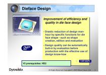
Dieface Design Improvement of efficiency and Improvement of efficiency and quality in die face design quality in die face design --Drastic reduction of design manDrastic reduction of design manhour by specific functions for die hour by specific functions for die face shape --such as shape face shape such as shape creation, edition and evaluation creation, edition and evaluation --Design quality can be automatically Design quality can be automatically bult-in by evaluation before bult-in by evaluation before production with the effective use of production with the effective use of design know-how...
Open the catalog to page 3
Dieface Design command Hole direction Hole direction 3D section 3D section creation creation Depth Measurement Depth Measurement Trim condition Trim condition 3D guide line 3D guide line creation creation Formability evaluation Bead Bead 2D guide 2D guide line creation line creation Auxiliary guide Auxiliary guide line creation line creation 2D section 2D section creation creation Layout support R attribute R attribute Vertical offset Vertical offset Flange expansion Flange expansion (curve) (curve) Flange expansion Flange expansion (surface) (surface) Extrapolated Extrapolated surface surface...
Open the catalog to page 4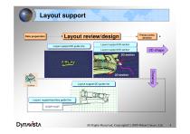
Layout support Data preparation Data preparation Primary press Primary press direction direction Layout review/design Layout support/3D guide line Layout support/3D guide line Layout support/3D section Layout support/3D section Layout support/2D section Layout support/2D section Layout support/2D guide line Layout support/2D guide line Layout support/auxiliary guide line Layout support/auxiliary guide line All Rights Reserved, Copyright(C) 2009 Nihon Unisys, Ltd.
Open the catalog to page 5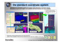
Die standard coordinate system -Definition of a coordinate system by varying a press direction in real time manner. -Evaluations (back draft, depth, trim condition and hole direction) are also available. Back draft An optimum press direction is determined after the evaluation (A new coordinate system will be created.) Trim condition Hole direction - Evaluation will be performed for the press direction. - Each of the evaluation items will be checked by the real-time rotation of the axis. All Rights Reserved, Copyright(C) 2009 Nihon Unisys, Ltd.
Open the catalog to page 6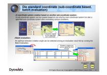
Direction decisicci | Evasion | Q Rotation View * Rortaticn Direction Axis System |A*is SySteirtS Ratatron axis cede* j x->\->Z Rotation center | NoSelectiorr Standard View Standard Direction]- RefllTirrt - Batch _Evaluate_ll _ Evafaatutt E^akjatior~i Pitch I Pvcf hone pbec... ' j"i>rer hang phccMnimum - |~ Dcojh: [teojh tata.. ~r I ii*CcrdH iomDcnss;.. Ti iniC O RotatBti Vierc t Relation Direcien Rotation axis ordal^^-
Open the catalog to page 7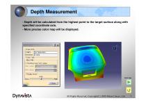
Depth Measurement - Depth will be calculated from the highest point to the target surface along with specified coordinate axis. - More precise color map will be displayed. All Rights Reserved, Copyright(C) 2009 Nihon Unisys, Ltd.
Open the catalog to page 8
Hole direction check Check if piercing is possible along with a specified direction, and display the check result on the screen and a list. Holes are automatically retrieved by specifying a product shape, and an arrow is displayed as follows. - yellow for dangerous angle - red for impossible angle - blue for safe angle -Two or more directions can be defined for a cam mechanism. - By “Automatic grouping”, holes are automatically collected as a group if they can be pierced along the specified angle. For other holes, new piercing angles will be automatically created for the grouping. All Rights...
Open the catalog to page 9
Spring Back Modification Type: Target Face: Rotation Bass Line: Section Base Line Type: Section Base Line: Chord Length Accuracy: ■Selection/Exclusion Reversal Input Section Base Line CreateFace £ m^ Face5prjngEai:k O not make Face Of SpringBack
Open the catalog to page 10
Extrapolated Surface - Create a surface by extending outer boundary curves of a composite surface. - Tangent continuity is secured between a specified surface and an extrapolated surface created . (1) Patch boundary is created between cross boundaries. Extend after separating bend portion (2) Tangent direction is neglected for cross boundaries. Range of extension is specified. Linear extension with G2 continuity at end portion. Constant surface width is possible. All Rights Reserved, Copyright(C) 2009 Nihon Unisys, Ltd.
Open the catalog to page 11
Extrapolated Surface Limiting points ■Start position: j'befault(None) Extrapolate length l~1 Constant distance optimisation Creation mode: Tangency angle: Tangent continuity Propagation mode: |Tangent Crossing edge Edges to disregard: |Default(None) Edges to keep: IDefault(None) □ Create gouge part as the other surface
Open the catalog to page 12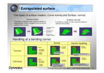
Extrapolated surface -Two types of surface creation, Curve normal and Surface normal. Curve normal Surface normal A surface is created so that a patch boundary is perpendicular to both a tangent to the curve and vertical to the surface. A surface is created so that a patch boundary is vertical to the surface Vertical to the surface A tangent to the curve Direction of surface creation Handling at a bending corner former Created surface Corner handling Boundary to extend Target surface Corner handling Boundary to extend Target surface Separated Smoothly connecting two surfaces Created surface Overlapped...
Open the catalog to page 13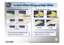
Vertical offset/Along-surface offset - Curve offset perpendicular to a surface - Curve offset along a surface Along surface Base line Along surface -- Two or more curves are allowed to input. Two or more curves are allowed to input. -- Two or more curves are allowed to input. Two or more curves are allowed to input. -- Variable offset value is possible. Variable offset value is possible. -- Variable offset value is possible. Variable offset value is possible. All Rights Reserved, Copyright(C) 2009 Nihon Unisys, Ltd.
Open the catalog to page 14All FTI Forming Technologies Incorporated catalogs and technical brochures
 CATBLANK AERO
2 Pages
 CATIA COSTOPTIMIZER Advanced
2 Pages
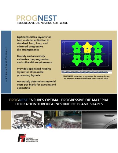
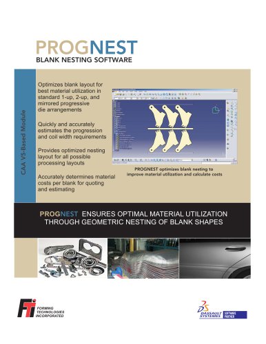 CATIA PROGNEST
2 Pages
 COSTOPTIMIZER Advanced
2 Pages
 DYNAVISTA Die Structure
31 Pages
 DYNAVISTA Dieface
20 Pages
 DYNAVISTA Fillet
29 Pages
 FASTFORM Advanced
2 Pages
 FASTFORM Multistage
2 Pages
 FASTIncremental
2 Pages
 FormingSuite Professional
2 Pages
 STRIPNEST
2 Pages
 CATBLANK
2 Pages
 CATFLANGE
2 Pages
 CATNEST
2 Pages
 PROGNEST
2 Pages
 FASTBLANK for Pro/ENGINEER
2 Pages
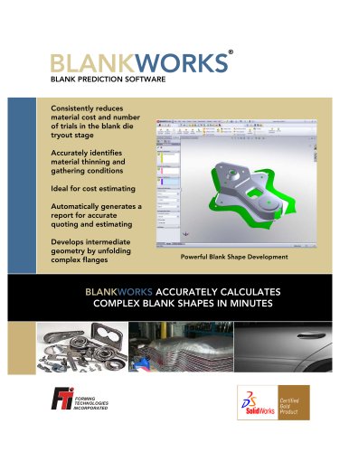 blankworks
2 Pages
 costoptimizer
2 Pages
 catprognest
2 Pages
 catstamp
2 Pages
 costoptad
2 Pages
 prognest
2 Pages
 blanknest
2 Pages
 professional
2 Pages
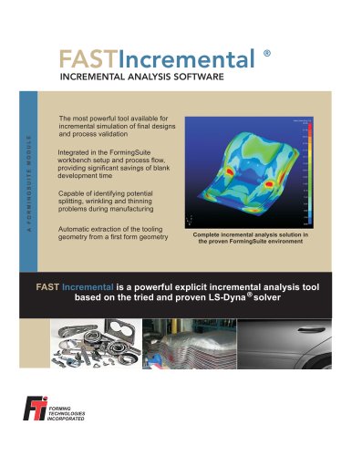 incremental
2 Pages
 multistage
2 Pages
 ffad
ffad2 Pages
 fastblank
2 Pages
- Analysis software solution
- Process software
- Real-time software
- Computer-aided design software
- Design software solution
- Simulation software solution
- Development software
- Engineering software
- Calculation software
- CAD/CAM software
- SolidWorks software
- Nesting software
- PLM software
- CATIA V5 software
- Cost estimation software
- Schema design software
- Stamping simulation software