- Catalogs
- FTI Forming Technologies Incorporated
- DYNAVISTA Die Structure
DYNAVISTA Die Structure
1 /31Pages
DYNAVISTA Die Structure
1 /31Pages
Catalog excerpts

V7.0 Die Structure Design May, 2006 Nihon Unisys, Ltd. All Rights Reserved, Copyright(C) 2006 Nihon Unisys, Ltd.
Open the catalog to page 1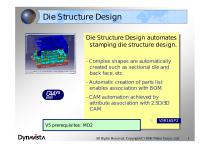
Die Structure Design Die Structure Design automates Die Structure Design automates stamping die structure design. stamping die structure design. --Complex shapes are automatically Complex shapes are automatically created such as sectional die and created such as sectional die and back face, etc. back face, etc. --Automatic creation of parts list Automatic creation of parts list enables association with BOM. enables association with BOM. --CAM automation achieved by CAM automation achieved by attribute association with 2.5D/3D attribute association with 2.5D/3D CAM CAM V5 prerequisites: MD2 All...
Open the catalog to page 2
Die Structure Design command Unite curves Unite curves Unite curves Unite curves Standard parts Standard parts placement placement Min/Max Box Min/Max Box Part attribute/BOM Part attribute/BOM Rib Through Rib Through Filling up Rib Filling up Rib Inside Rib Inside Rib Pierce list Pierce list Height dimension Height dimension Thickness Check Thickness Check 3D Note/View Change 3D Note/View Change Post process association SpecTable SpecTable Calculate Projection Area Calculate Projection Area Pierce placement Pierce placement Machining attribute Machining attribute Layer table Layer table V7.0...
Open the catalog to page 3
Unite curves - Smoothly connecting two or more curves into one All Rights Reserved, Copyright(C) 2006 Nihon Unisys, Ltd.
Open the catalog to page 4
Create PF offset curve - Creation of a curve by offsetting a profile curve on a surface which is internally created by parallel sweep of given profile curve. A surface internally created Offset Gouges are automatically detected and removed. Gouges are automatically detected and removed. All Rights Reserved, Copyright(C) 2006 Nihon Unisys, Ltd.
Open the catalog to page 5
Sectional die - Sectional die shape creation by sweeping a cross section line along profile curves. -- Removal of gouges Removal of gouges -- Assurance of surface width Assurance of surface width All Rights Reserved, Copyright(C) 2006 Nihon Unisys, Ltd.
Open the catalog to page 6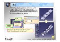
Rib -A rib is created by sweeping a top surface to specified sweeping direction, where the surface is created by offsetting specified curves to both sides with the direction determined by the curve direction and sweeping direction. -A curve not on plane can be specified. Curve direction Sweeping direction Thickness direction Thickness direction is perpendicular to both curve direction and sweep direction. All Rights Reserved, Copyright(C) 2006 Nihon Unisys, Ltd.
Open the catalog to page 7
Rib Through Dynavista only For air escape when up die goes down, casting hole is needed. The casting hole also is to reduce die weight. Manually creating this casting hole takes time. Concept Create removing solid easily Create pocket and sketch of the pocket by minimum input Operation (1) specify support plane of sketch (2) Specify outer curves for creating pocket (3) Input offset value from outer curves specified in step (2) The offset curves will be used as profile of pocket (4) Specify start position and end position of casting hole Characteristic - Manually creating of sketch for casting...
Open the catalog to page 8
Filling up gap Dynavista only Background Casting sand will be burnt on interstice of die body. To avoid the casting sand, it is necessary to fill up interstice in design process. It takes long time to fill up all interstice. Function outline Easily creating filling solid Using CATIA sketch and pad as output result Operation (1)Specify base plan and position for sketch (2)Input H,V direction of sketch plane (3) Input height of pad (1)Specify plane for sketch (2)Specify walls (3)Input thickness and height of pad Reference position Standing wall Thickness Filling direction Reference plane Reference...
Open the catalog to page 9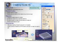
Creating inside rib Dynavista only Background Creating rib in die design takes time Function Outline Create inside rib easily. Create pad and sketch of the inside rib by minimum input Operation (1)Specify support plane for sketch (2) Specify 4 base lines to decide inside rib (3) Input number of inside rib and interval of inside rib (4)Input parameters for pad Characteristic - Manually creating of sketch and pad is not needed -Inside rib will be created by CATIA sketch and pad, it is easy for uses to edit Base line +V Support plane Output Base line -H All Rights Reserved, Copyright(C) 2006 Nihon...
Open the catalog to page 10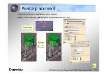
Pierce placement -Placement of a pierce part based on its symbol Modification of pierce type and pierce parameter are possible. All Rights Reserved, Copyright(C) 2006 Nihon Unisys, Ltd.
Open the catalog to page 11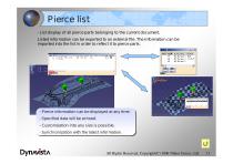
Pierce list - List display of all pierce parts belonging to the current document. Listed information can be exported to an external file. The information can be imported into the list in order to reflect it to pierce parts. -- Pierce information can be displayed at any time. Pierce information can be displayed at any time. -- Specified data will be echoed. Specified data will be echoed. -- Customization into any size is possible. Customization into any size is possible. -- Synchronization with the latest information. Synchronization with the latest information. All Rights Reserved, Copyright(C)...
Open the catalog to page 12
AHIS system Chantic i i?v n.nrn, F.-I *-P ?F m, "i.nrrij Ts.rrr ■- ?F in >:v ■ ni.-m, n.nrn, Krn.rrr i.:r iv i.nm, .Ti.rrn -=r in
Open the catalog to page 13
Standard parts placement - A standard part is selected from a catalog and its instance is placed at specified position. All Rights Reserved, Copyright(C) 2006 Nihon Unisys, Ltd.
Open the catalog to page 14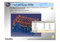
Part attribute/ BOM -Information such as part identifier, material, order information, heat treatment, etc. can be defined as part attributes. - BOM is created using the part attributes. - The attributes can be customized by exporting to the Excel file. All Rights Reserved, Copyright(C) 2006 Nihon Unisys, Ltd.
Open the catalog to page 15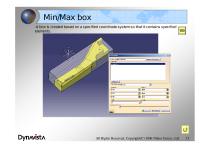
Min/Max box -A box is created based on a specified coordinate system so that it contains specified elements. All Rights Reserved, Copyright(C) 2006 Nihon Unisys, Ltd.
Open the catalog to page 16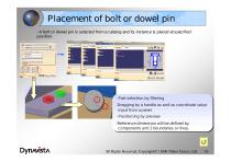
Placement of bolt or dowel pin - A bolt or dowel pin is selected from a catalog and its instance is placed at specified position. -- Part selection by filtering Part selection by filtering -Dragging by a handle as well as coordinate value -Dragging by a handle as well as coordinate value input from a panel. input from a panel. -- Positioning by preview Positioning by preview -Reference dimension will be defined by -Reference dimension will be defined by components and 2 boundaries or lines. components and 2 boundaries or lines. All Rights Reserved, Copyright(C) 2006 Nihon Unisys, Ltd.
Open the catalog to page 17All FTI Forming Technologies Incorporated catalogs and technical brochures
 CATBLANK AERO
2 Pages
 CATIA COSTOPTIMIZER Advanced
2 Pages
 CATIA PROGNEST
2 Pages
 COSTOPTIMIZER Advanced
2 Pages
 DYNAVISTA Dieface
20 Pages
 DYNAVISTA Fillet
29 Pages
 DYNAVISTA Shaper
65 Pages
 FASTFORM Advanced
2 Pages
 FASTFORM Multistage
2 Pages
 FASTIncremental
2 Pages
 FormingSuite Professional
2 Pages
 STRIPNEST
2 Pages
 CATBLANK
2 Pages
 CATFLANGE
2 Pages
 CATNEST
2 Pages
 PROGNEST
2 Pages
 FASTBLANK for Pro/ENGINEER
2 Pages
 blankworks
2 Pages
 costoptimizer
2 Pages
 catprognest
2 Pages
 catstamp
2 Pages
 costoptad
2 Pages
 prognest
2 Pages
 blanknest
2 Pages
 professional
2 Pages
 incremental
2 Pages
 multistage
2 Pages
 ffad
ffad2 Pages
 fastblank
2 Pages
- Analysis software solution
- Process software
- Real-time software
- Computer-aided design software
- Design software solution
- Simulation software solution
- Development software
- Engineering software
- Calculation software
- CAD/CAM software
- SolidWorks software
- Nesting software
- PLM software
- CATIA V5 software
- Cost estimation software
- Schema design software
- Stamping simulation software