- Catalogs
- Frontier Electronics, Corp.
- Magnetic Components
Magnetic Components
1 /198Pages

Magnetic Components
1 /198Pages
Catalog excerpts

Air Coils Power Inductors Tunable Inductors Common Mode Chokes Switching Transformers & PFC Chokes Wire Wound & Thin Film Chip Inductors RoHS Compliant Halogen-Free DESIGNING THE CUTTING EDGE
Open the catalog to page 1
THE NEW FRONTIER OF PASSIVE COMPONENTS — Designing the Cutting Edge — About Frontier Electronics Frontier Electronics was formed in 1972 as a leading designer and manufacturer of magnetic products. Over the years we have expanded our product offerings to include MLCCs, IPCs and Diodes while continuing to expand our lines of inductors, coils and transformers. We offer a vast array of industry standard products supported by our expansive manufacturing resources worldwide. Furthermore, Frontier has proven successful in the design and manufacturing of custom products to help our customers succeed. Frontier’s...
Open the catalog to page 2
667 E. Cochran Street, Simi Valley, CA 93065 www.frontierusa.comTel: (805)
Open the catalog to page 5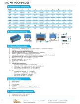
Foot Print C. General Information: 1. Series: 29***-xx_, “29***” = Series, “xx” = dash number, “_” = Inductance Tolerance. 3. Small and lightweight surface mounting type 4. Maximum Temperature Rise: 15°C (when measured at 25°C ambient). 5. High Q at high frequency and High self-resonance frequency 6. Inductance & Q measured with HP4291B Impedance Analyzer with HP16193 test fixture 7. SRF measured using the HP8753E Network Analyzer or equivalent. 8. DCR measured using the Chroma 16502 or equivalent 12. Inductance and Current range: 5. Mobile Communication Devices (Cell Phones, Radios, etc.) 1....
Open the catalog to page 6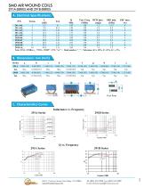
B. Dimensions: mm (Inch) Series Foot Print C. Characteristics Curve: Inductance vs. Frequency 667 E. Cochran Street, Simi Valley, CA 93065 www.frontierusa.com
Open the catalog to page 7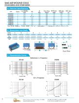
Q Test Freq. DCR max. SRF min. I DC max. Min. (MHz) (mQ) (GHz) (A) Dash number, “_” = Tolerance, K= ± 10%, J= ±5%, G= ± 2%. B. Dimensions: mm (Inch) Series 292AR Tol. 292BR Tol. C. Characteristics Curve: Inductance vs. Frequency
Open the catalog to page 8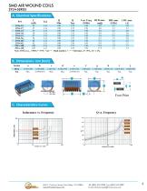
B. Dimensions: mm (Inch) g h i j Foot Print C. Characteristics Curve: Inductance vs. Frequency
Open the catalog to page 9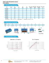
Q Test Freq. DCR Max. SRF Min. I DC Max. Typ. (MHz) (mi) (MHz) (A) Dash number, “_” = Tolerance, J= ±5%, G= ± 2%. Foot Print C. Characteristics Curve:
Open the catalog to page 10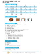
B. Mechanical Drawing:C. General Information: ^ 1. P/N: LSQ****A-xxx_, “LSQ****A” = Series, “xxx” = Inductance, “_” = Tolerance. 4. Small and lightweight surface mounting type 5. High Q at high frequency 6. High self-resonance frequency 7. Maximum Temperature Rise: 15°C (when measured at 25°C ambient). 8. Inductance & Q measured with HP4291B Impedance Analyzer with HP16193 test fixture 9. SRF measured using the HP8753E Network Analyzer or equivalent. 10. DCR measured using the Chroma 16502 or equivalent. 14. Inductance and Current range: 5. Mobile Communication Devices (Cell Phones, Radios)...
Open the catalog to page 11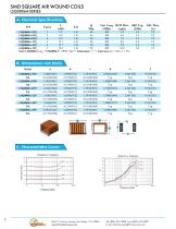
SMD Square Air Wound Coils LSQ0806A-Series B. Dimensions: mm (Inch) Series 667 E. Cochran Street, Simi Valley, CA 93065 SMD SQUARE AIR WOUND Tel: (805) 522-9998 Fax: (805) 522-9989 COILS www.frontierusa.com E-mail: frontiersales@fro
Open the catalog to page 12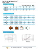
Note: LSQ0807A-xxx_, “LSQ0807A” = P/N, “xxx” = Inductance, “_” = Tolerance, K: ± 10%, J: ± 5%. Series a b c d e f
Open the catalog to page 13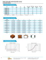
Note: LSQ0908A-xxx_, “LSQ0908A” = P/N, “xxx” = Inductance, “_” = Tolerance, K: ± 10%, J: ± 5%. Series a b c d e
Open the catalog to page 14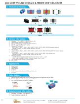
SMD Wire Wound Ceramic & Ferrite Chip Inductors C. Mechanical Drawing: Game Consoles Set Top Boxes Cables Modems Computers Mobile Communication Devices (Cell Phones, Radios, etc.) RF Filters Parts are marked with 3 color dots. The table below shows the significance of each color. Dots 1 and 2 indicate the inductance in nano-Henries. Dot 3 indicates number of zeroes to be added. 0 = Black 1 = Brown 2 = Red 3 = Orange 4 = Yellow 5=Green 6=Blue 7 = Violet 8 = Gray 9 = White G. Supplementary Information: 1. Packaging Information (See Appendix A) 2. Solder Profile (See Appendix B) 667 E. Cochran Street,...
Open the catalog to page 16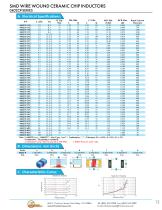
Note: 1. 0402CP-xxx_, “0402CP” = Size Type, “xxx” = Inductance, “_” = Tolerance, K= ± 10%, J= ±5%, G= ± 2%. Termination: Tin plating is standard. 2. Inductance & Q-value measured at 250 MHz 3. 0402CP has no color code. Series a b c d 667 E. Cochran Street, Simi Valley, CA 93065 www.frontierusa.com
Open the catalog to page 17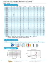
p L Q min. Test Freq. 900(MHz) 1.7(GHz ) SRF Min. DCR Max. I rms. Color P/N (nH) 1 ol. Typ. (MHz) L typ. Q typ. L typ. Q typ. (GHz) (Q) Max.(mA) code C. Characteristics Curve: 667 E. Cochran Street, Simi Valley, CA 93065 www.frontierusa.comTel: (805) 522-9998 Fax: (805) 522-9989 E-mail: frontiersales@frontit rusa.com 13
Open the catalog to page 18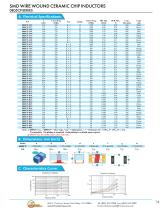
Color code White Brown Gray Blue White Black Violet Brown Green Red Red Orange Orange Yellow Green Blue Gray Violet Gray Yellow Green Blue White Yellow Black Brown Red Orange Black Yellow Brown Green Blue Violet Red Gray Red Yellow White Gray Black Orange Brown White Violet Orange Yellow Green Brown Note: 1. 0805CP-xxx_, “0805CP” = Size Type, “xxx” = Inductance, “_” = Tolerance, K= ± 10%, J= ±5%, G= ± 2%. Termination: Tin plating is standard. Gold plating is available upon request. 2. 0805CP has first inductance color code only. 667 E. Cochran Street, Simi Valley, CA 93065 www.frontierusa.com...
Open the catalog to page 19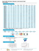
, “1008CP” = Size Type, “xxx” Tin plating is standard. Gold = Inductance, = Tolerance, K plating is available upon request. Series a b c d e f Parts are marked with 3 color dots. The table below shows the significance of each color. Dots 1 and 2 indicate the inductance in nano-Henries. Dots 3 indicate number of zeroes to be added. 0 = Black 5=Green 667 E. Cochran Street, Simi Valley, CA 93065 www.frontierusa.com Tel: (805) 522-9998 Fax: (805) 522-9989 E-mail: [email protected] 15
Open the catalog to page 20All Frontier Electronics, Corp. catalogs and technical brochures
 LP3800K0603BT
2 Pages
 LP5900E0805AT
2 Pages
 LP5900M0805AT
2 Pages
 LP2500E0805AT
2 Pages
 LP2500K0603CT
2 Pages
 LP2500K0603BT
2 Pages
 LP2500K0603AT
2 Pages
 LP2500M0402CT
2 Pages
 LP2500M0402BT
2 Pages
 LP2500M0402AT
2 Pages
 LP2500E0805BT
2 Pages
 LP1910M0603BT
2 Pages
 LP1910M0402BT
2 Pages
 LP1910M0402AT
2 Pages
 LP0915E0805AT
2 Pages
 LP0915M0603AT
2 Pages
 LP0915M0402AT
2 Pages
 MBR10L45FCT
2 Pages
 GP02-25
2 Pages
 BCT8-005
2 Pages
 Multi Layer Ceramic Capacitors
24 Pages