- Catalogs
- The Fredericks Company
- TrueTILT? Wide Range 0717-4304-99
TrueTILT? Wide Range 0717-4304-99
1 /1Page

TrueTILT? Wide Range 0717-4304-99
1 /1Page
Catalog excerpts

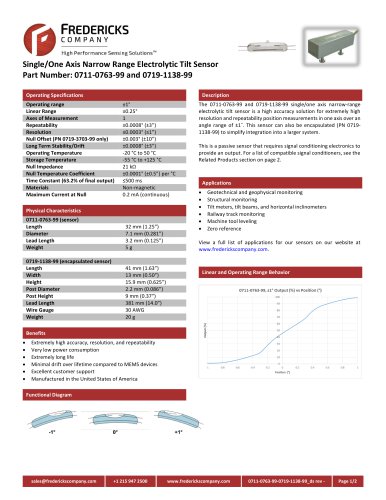
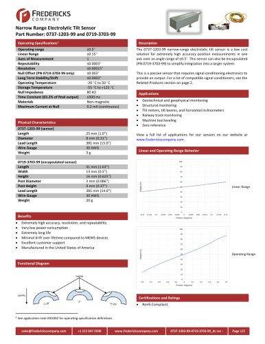
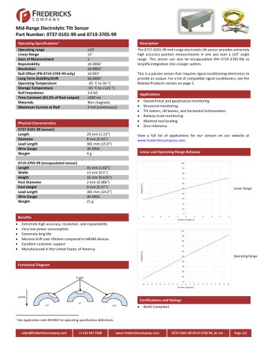
DATA SHEET The 0717-4304-99 TrueTilt Sensor” represents a new advancement in electrolytic tilt sensor technology. Robust all metal construction provides durability as well as superior dimensional tolerances, which equates to excellent sensor-tosensor electrical performance. This sensor is ideal for economical, commercial market applications requiring high production quantities and first-rate accuracy. Angle Range Resolution Repeatability Applications Include Wheel Alignment Navigation and GPS Compensation Automotive Roll Over Game Controllers and Joysticks Medical and Physical Feedback Instruments Physical Dimensions Height Diameter – Cap Diameter Flange Lead Length Lead Diameter Lead Spacing (center to center) Sensor Test Circuitry Tests were conducted by exciting the outer electrodes of a single axis with an AC signal of 400 Hz and an rms voltage to produce the maximum current at null as per operating specifications. Output readings are taken between the center electrode and the center of the balanced resistors R1 and R2. Tests were conducted at a temperature of +25 C. See test circuitry in figure 3. Output curve is shown in figure 1. 60 Operating Range (max.) Linear Range ± 25° Null Voltage ≤0.025 Volts Null Current(max.) 0.2 mA (continuous) Null Impedance (nom) 40 K Ohms (25°C) (measured left to right electrode)see fig. 2 Repeatability 0.1° Resolution < 0.2 arc minutes Symmetry (typ) 5% Null Offset (max) 5.0° Mech. Crosstalk/Deg. (to 20°) 0.025° Temperature coefficient Null 20 arc sec /°C Scale 0.1% /°C Stability @24 Hrs. 0.1° -40 C to +85 C Operating Temperature -55 C to +100 C Storage Temperature Time Constant (1) < 100 msec Materials magnetic NOTE: Output sensitivity’s scale factor may be modified to individual requirements upon special order. OUTPUT SENSITIVITY Figure 1 100 PERCENT OUTPUT Operating Specifications Descrition of Test Values Eout = Angle of tilt from null (Direction of tilt determined by phase of Eout) R1 =R2 = ½ Null Impedance (nom) Caution!-Ensure that all test and operating circuits are entirely free of direct current. Direct current will cause level damage and/or instability. IMPEDANCE vs TEMPERATURE Figure 2 IMPEDANCE (KOhms) AC input voltage = Null Current (max) times Null Impedance (nom) 0 TILT ANGLE (degrees) The Fredericks Company l 2400 Philmont Ave ● HuntingdonValley, PA 19006-0067 Tel: 215.947.2500 l Fax: 215.947.7464 l Email: [email protected] l www.frederickscom.com 0717-4304-99data sheet Revision: A
Open the catalog to page 1All The Fredericks Company catalogs and technical brochures
 Televac br5003
6 Pages
 Televac MP7FR Cold Cathode
2 Pages
 Televac MX4A Convection
2 Pages


Archived catalogs
 2 A Thermocouple Sensor
2 Pages
 Single Axis Narrow Angle
1 Page
 0711-0768-99-0719-1143-99_ds
2 Pages
 Electrolytictilt
4 Pages
 0703-0703-99 TrueTilt
2 Pages


- Communication gateway
- Tilt sensor
- Industrial gateway
- Ethernet gateway
- Serial gateway
- Digital inclination sensor
- 2-axis tilt sensor
- RS-485 gateway
- MEMS inclination sensor
- Signal conditioner
- Multi-axis tilt sensor
- Analog inclination sensor
- High-precision tiltmeter
- 1-axis tilt sensor
- IP67 inclination sensor
- Sensor signal conditioner
- Vacuum sensor
- Analog signal conditioner
- Tilt switch
- RS-485 inclinometer