
- Catalogs
- Franz Binder GmbH + Co. Elektrische Bauelemente KG
- Automation Technology Sensors & Actuators


- Company
- Products
- Catalogs
- News & Trends
- Exhibitions
Automation Technology Sensors & Actuators

Automation Technology Sensors & Actuators
- M5 Series (707): Features screw locking connectors with IP67 protection, available in 3 and 4 contact versions, with cable lengths of 2m and 5m. UL approved.
- M8 Series (768, 718): Offers connectors with screw or snap-in locking, IP65/IP67/IP69K protection, and metal housing with EMC shielding. Available in 2m and 5m lengths, suitable for chain flex applications. UL approved.
- M12-A Series (713, 763): Includes connectors with screw locking, IP67/IP68/IP69K protection, and options for food and beverage applications. Available with transparent housings and LED displays. UL approved.
- Connectors adhere to DIN EN 61076-2-105 standards for screw locking.
- Protection standards are explained in the technical information section.
- Further cable lengths are available upon request for all series.
- For specific applications, such as food and beverage, specialized connectors are recommended.
- Connectors are available in various configurations with different numbers of contacts and cable lengths.
- Materials used include brass and bronze for contacts, with gold plating for enhanced conductivity.
- Temperature ranges and mechanical operation cycles are specified for durability and performance assurance.
- Ensure compatibility with the required degree of protection (IP ratings) for specific environments.
- Consider the mechanical and electrical specifications, such as rated voltage and current, for application suitability.
The document provides detailed specifications for cable connectors used in automation technology. Key parameters include wire gauge options of 0.34 mm² (AWG 22) and 0.25 mm² (AWG 24), with standard cable lengths of 2 m and 5 m, though other lengths are available upon request. The connectors are designed for a degree of protection rated at IP67 and IP69K, ensuring durability in various environments. They support over 100 mating cycles and operate within a temperature range of -25°C to +85°C. Rated voltage is specified at 60 V, with a rated impulse voltage of 1500 V.
Materials:
The connectors are constructed using materials such as brass (CuZn) for the contact body, with gold (Au) plating for enhanced conductivity. The housing is made from PUR, providing flexibility and resistance to mechanical stress.
Procedures:
Assembly instructions for cable connectors include steps for both screw and solder versions. The process involves dismantling the cable, stripping and connecting wires, and securing the components with a pressing screw. Specific torque values are provided for different connector types.
Standards and Approvals:
The connectors comply with UL/CSA standards, ensuring they meet safety and performance requirements. The document also references comparable AWG conductors and provides guidelines for cable bending radius and temperature ranges for both moving and static cables.
Recommendations:
For optimal performance, it is recommended to adhere to the specified bending radius and temperature limits. The document suggests using the connectors in chain flex applications or when mechanically stressed at temperatures up to +60°C.
- Shield Diameter ≤ 3.5 mm: Pre-assemble the housing on the cable, dismantle the cable, strip wires, shorten the shielding braid, wrap with copper tape, screw on wires, attach the sleeve to the insert, and tighten the pressing screw.
- Shield Diameter > 3.5 mm: Similar steps as above, with adjustments for larger diameter.
Assembly Instructions for Angled Connectors:
- Thread pressing screw, pinch ring, seal, and shielding ring onto the cable, dismantle the cable, strip and solder wires, assemble components, and tighten screws.
Technical Specifications:
- Attenuation Curve: Follows DIN 47250-6 standards for straight cable connectors, with specific attenuation values across frequencies.
- Contact Arrangements: Various configurations available, including 3, 4, 5, 6, 8, and 12 contacts, with color-coded wiring.
Installation Proposals:
- Three installation proposals for M8 panel mount connectors, detailing dimensions and tightening torques.
Accessories:
- Protection caps for male and female cable connectors and panel mount connectors, with specific ordering numbers.
- Number of Contacts: Options include 4, 5, 8, and 12 contacts.
- Connector Locking System: Utilizes screws for secure connections.
- Termination: Single wires (Litzen) with wire gauges of 0.25 mm² (AWG 24) and 0.14 mm² (AWG 26).
- Degree of Protection: Rated IP67, IP68, and IP69K for outdoor applications, ensuring resistance to dust and water.
- Mechanical Operation: Over 100 mating cycles.
- Temperature Range: Operates between -40°C and +85°C, with some outdoor models rated up to +100°C.
- Rated Voltage: 250 V, 60 V, and 30 V, with impulse voltages of 2500 V, 1500 V, and 800 V.
- Pollution Degree: Rated at level 3.
- Overvoltage Category: Category II.
- Material Group: Group II.
- Rated Current (40°C): 4 A (3 A UL), 2 A (1.5 A UL), and 1.5 A.
- Contact Material: Options include CuSn (Bronze) and CuZn (Brass).
- Contact Plating: Gold (Au) plating for enhanced conductivity and corrosion resistance.
- Contact Body Material: PA (Polyamide).
- Housing Material: Options include metal housing, zinc die-cast nickel-plated, and stainless steel.
- Locking Material: Various materials depending on the model.
- Electrical Ratings: Rated voltage ranges from 30V to 250V, with impulse voltages up to 2500V. Rated current varies from 1.5A to 4A depending on the configuration.
- Materials: Contacts are made of brass (CuZn) or bronze (CuSn) with gold plating. The housing is typically made of PUR or PA, with locking mechanisms in zinc die-cast nickel-plated material.
- Mechanical Properties: Connectors are designed for over 100 mating cycles and can operate in temperatures ranging from -25°C to +90°C. They are rated for IP68/IP69K protection, indicating high resistance to dust and water ingress.
- Wire Gauge: Options include 0.34 mm² (AWG 22) and 0.25 mm² (AWG 24).
- Jacket Material: Available in PVC or PUR, with temperature ranges from -50°C to +105°C depending on the material.
- Resistance and Flexibility: Wire resistance is specified at 60 Ω/Km at 20°C. Cables are designed for a minimum bending radius of 5xD to 10xD and can withstand millions of bending cycles.
- Connector Types: Includes male and female inserts, protection caps, and sleeves.
- Termination Types: Solder and screw clamp connections.
- Shielding: Options for shieldable and non-shieldable connectors.
- Materials: Threaded rings made from plastic, zinc diecasting, and stainless steel.
- Torque Specifications: Various torque settings for different components, e.g., 0.4 Nm for 4-5 pole wires, 0.2 Nm for 8 pole wires.
- General Steps: Involves threading components onto the cable, dismantling the cable, stripping wires, and securing them with appropriate torque.
- Shielding Instructions: For shieldable connectors, includes steps for shortening the shield and wrapping with copper tape if necessary.
- Specific Instructions: Detailed steps for different connector types, including the use of opening tools for wire insertion.
- Ensure correct torque settings to avoid damage.
- Follow specific instructions for shieldable connectors to maintain shielding integrity.
- Use appropriate materials for environmental conditions, such as stainless steel for outdoor applications.
- Cable Diameters: Ranges from 2.1 mm to 10 mm depending on the connector type.
- Shielding Braid Diameter: Instructions vary for diameters above and below 5.5 mm.
- Angled connectors are available with screw clamp connections, solder terminations, and crimp connections. They can be shieldable with 4, 5, 8, or 12 contacts.
- Panel mount connectors include male and female inserts, with options for outdoor use and rectangular flanges.
- Torque specifications for pressing screws range from 0.8 to 1.0 Nm, depending on the connector type.
- Angled Connectors: The procedure involves threading components like the pressing screw, pinch ring, seal, and shielding ring onto the cable, dismantling and stripping the cable, soldering or screwing the wires, and securing the housing with the insert.
- Panel Mount Connectors: The assembly includes fastening the connector in the panel cut-out, inserting the male or female insert, and securing with a hexagonal nut if necessary.
- For cables with a shielding braid diameter greater than 5.5 mm, the braid should be shortened and wrapped with copper tape if needed.
- For diameters less than or equal to 5.5 mm, the braid should be reverted to the cable and wrapped with copper tape.
- Ensure proper torque is applied to pressing screws to avoid damage.
- During disassembly, avoid pulling on single wires to prevent damage to contacts.
- Use protection caps when mating connectors are not used to protect the connectors.
- Always follow the specified torque settings for different connector types to ensure secure connections.
- Proper handling of shielding and cable stripping is crucial for maintaining signal integrity and preventing interference.
- For SMT contact inserts, solder them to the PCB using an appropriate soldering method.
- Fasten the panel mount connector sleeve into the panel cut-out.
- Guide the SMT contact insert through the panel mount connector sleeve.
- For female parts, thread the o-ring onto the contact carrier and push it to the bottom with a suitable tool.
- Fit the o-ring 12 x 1 onto the female panel mount connector sleeve and push it into the groove.
- Push the sleeve through the mounting wall, align it, and tighten the nut.
- Insert the female insert into the sleeve and thread the o-ring 7 x 1.2 onto it.
- Attenuation curves are provided according to DIN 47250-6 for various cable connector types, including those with shielding rings and iris type springs.
- Contact arrangements are detailed for different pole versions, including 3, 4, 5, 8, and 12 contacts.
- Requirements for IP67 protection include using specific sealing for metal and plastic housings.
- Details on tightening torque and wall thickness for different housing materials are provided.
- Drilling schemes for male and female inserts are provided for both metal and SMT PCB mounting, with and without shielding sheets.
Catalog excerpts

SENSORIK & AKTORIK SENSORS & ACTUATORS
Open the catalog to page 1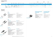
Inhaltsverzeichnis Contents am Kabel angespritzt moulded connectors Anschlussart Termination Serie Series Seite Page Schutzart Degree of protection Spannung Voltage Strom Current löten solder schrauben screw crimpen crimp Käfigzugfeder Wire clamp Verriegelung Locking schrauben screw Bajonett Bayonet schnapp snap-in Push-Pull Push-Pull Automatisierungstechnik – Sensorik & Aktorik Automation Technology – Sensors & Actuators M5 M8 M12-A Zubehör für M12 Verbindungsleitungen und Verteiler M5 M8 M12-A Accessories for M12 Connecting Cables and Distributors Übersicht Summary M5 Serie 707 Steckverbinder...
Open the catalog to page 2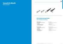
Sensorik & Aktorik Sensors & Actuators M5 Automatisierungstechnik M5 Automation Technology Kabelsteckverbinder • Schraubverriegelung nach DIN EN 61076-2-105 • 3- und 4-polig • Schutzart IP67 1) • Am Kabel angespritzte Ausführungen • Gewindering mit Rüttelsicherung Cable Connectors • Screw locking according to DIN EN 61076-2-105 • 3 and 4 contacts • Degree of protection IP67 1) • Moulded versions • Thread nut with immunity to vibration Flanschsteckverbinder • Schraubverriegelung nach DIN EN 61076-2-105 • 3- und 4-polig • Schutzart IP67 1) • Einfache Montage • Löt-/Tauchlötanschluss/Litzen • Verschiedene...
Open the catalog to page 3
M5 Flanschstecker, tauchlöten Male panel mount connector, dip solder Einbaustecker für Sensor-Rohrmontage, Rohr-Ø 3,75–H7 Male receptacle for sensor tubes, tube Ø 3,75–H7 Flanschdose mit Litzen Female panel mount connector with single wires Flanschdose, von vorn verschraubbar, mit Litzen Female panel mount connector, front fastened, with single wires Bohrbilder siehe Seite 10 Drilling schemes see page 10 Bohrbilder siehe Seite 10 Drilling schemes see page 10 Bestell-Nr. Ordering-No. Polzahl Contacts Bestell-Nr. Ordering-No. Polzahl Contacts Bestell-Nr. Ordering-No. Polzahl Contacts Polzahl Steckverbinder...
Open the catalog to page 4
Kabeldose, umspritzt, M5 x 0,5, geschirmt Female cable connector, moulded, M5 x 0,5, shielded Kabellänge Cable length Polzahl Contacts Kabellänge Cable length Number of contacts Connector locking system Termination Wire gauge Cable outlet Degree of protection Mechanical operation Upper temperature Lower temperature Rated voltage Rated impulse voltage Pollution degree Overvoltage categorie Material group Rated current (40 °C) Material of contact Contact plating Material of contact body Material of housing Material of locking Polzahl Steckverbinder Verriegelung Anschlussart Anschlussquerschnitt...
Open the catalog to page 5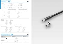
Automatisierungstechnik Automation Technology Polbilder Contact arrangements Stifteinsatz (Steckseite) Male insert (mating side) Buchseneinsatz (Steckseite) Female insert (mating side) braun/brown nicht konfektioniert/not assembled blau/blue schwarz/black braun/brown weiß/white blau/blue schwarz/black Bohrbilder Stifteinsatz (Leiterplatte), Schirmblechvariante Drilling schemes male insert (PCB), shielding sheet braun/brown weiß/white blau/blue schwarz/black braun/brown nicht konfektioniert/not assembled blau/blue schwarz/black Bohrbilder Buchseneinsatz (Leiterplatte), Schirmblechvariante Drilling...
Open the catalog to page 6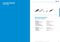
Sensorik & Aktorik Sensors & Actuators M8 Automatisierungstechnik M8 Automation Technology Kabelsteckverbinder • Schraubverriegelung nach DIN EN 61076-2-104 • Schutzart IP65/IP67 1) • Am Kabel angespritzte Ausführungen • Einfache Montage • Sehr gute EMV Eigenschaften (360° Schutz bei Schirmring Version) • Ausführungen mit Schirmringen/Irisfeder • Winkelsteckverbinder in 2–4 Positionen einstellbar Cable Connectors • Screw locking according to DIN EN 61076-2-104 • Degree of protection IP65/IP67 1) • Moulded versions • Easy assembly • Excellent EMC shielding (versions with shielding rings 360°)...
Open the catalog to page 7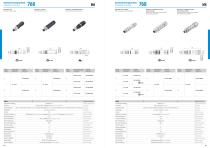
768 Kabelstecker, Schraubklemmanschluss, Irisfeder, schirmbar Male cable connector, screw clamp connection, iris type spring, shieldable Kabelstecker, Schraubklemmanschluss, mit Schirmring, schirmbar Male cable connector, screw clamp connection, with shielding ring, shieldable Kabelstecker, löten, schirmbar Male cable connector, solder, shieldable Automatisierungstechnik Automation Technology Kabelstecker, Schneidklemmanschluss Male cable connector, IDT connection Kabelstecker, schrauben Male cable connector, screw Kabelstecker, löten Male cable connector, solder Automatisierungstechnik Automation...
Open the catalog to page 8
768 Winkelstecker, löten, schirmbar Male angled connector, solder, shieldable Kabeldose, Schneidklemmanschluss Female cable connector, IDT connection Kabeldose, schrauben Female cable connector, screw Kabeldose, löten Female cable connector, solder Winkelstecker, Schraubklemmanschluss Male angled connector, screw clamp connection Automatisierungstechnik Automation Technology Winkelstecker, löten Male angled connector, solder Automatisierungstechnik Automation Technology Polzahl Contacts Kabeldurchlass Cable outlet Bestell-Nr. Ordering-No. Polzahl Contacts Polzahl Steckverbinder Verriegelung Anschlussart...
Open the catalog to page 9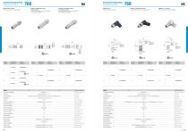
Polzahl Contacts Kabeldurchlass Cable outlet Bestell-Nr. Ordering-No. Polzahl Contacts Kabeldurchlass Cable outlet Polzahl Contacts Polzahl Steckverbinder Verriegelung Anschlussart Anschlussquerschnitt Kabeldurchlass Schutzart Mechanische Lebensdauer Obere Grenztemperatur Untere Grenztemperatur Bemessungsspannung Bemessungs-Stoßspannung Verschmutzungsgrad Überspannungskategorie Isolierstoffgruppe Bemessungsstrom (40°C) Material Kontakt Kontaktoberfläche Material Kontaktkörper Material Gehäuse Material Verriegelung Bestell-Nr. Ordering-No. Polzahl Contacts Kabeldurchlass Cable outlet Bestell-Nr....
Open the catalog to page 10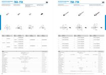
Polzahl Contacts Bestell-Nr. Ordering-No. Polzahl Contacts Bestell-Nr. Ordering-No. Polzahl Contacts Polzahl Contacts Polzahl Steckverbinder Verriegelung Anschlussart Anschlussquerschnitt Kabeldurchlass Schutzart Mechanische Lebensdauer Obere Grenztemperatur Untere Grenztemperatur Bemessungsspannung Bemessungs-Stoßspannung Verschmutzungsgrad Überspannungskategorie Isolierstoffgruppe Bemessungsstrom (40°C) Material Kontakt Kontaktoberfläche Material Kontaktkörper Material Gehäuse Material Verriegelung Polzahl Contacts Bestell-Nr. Ordering-No. Polzahl Contacts Polzahl Contacts Bestell-Nr. Ordering-No....
Open the catalog to page 11All Franz Binder GmbH + Co. Elektrische Bauelemente KG catalogs and technical brochures
 Miniature / Miniatur
172 Pages
 Product Portfolio
15 Pages
 General catalogue
954 Pages
 Core Program
236 Pages
 Automation Data transmission
61 Pages
 Medical Applications
23 Pages
 Power
Power37 Pages
 Subminiature
37 Pages
 about us.
9 Pages
 News
News23 Pages

- Data connector
- Electrical power supply connector
- Metal connector
- Polymer connector
- Circular connector
- Screw-in connector
- Socket electrical connector
- IP67 connector
- Rectangular connector
- Male connector
- Straight connector
- RF connector
- Screw connector
- DIN connector
- Nickel-plated brass connector
- Crimp connector
- Plug-in connector
- Right-angle electrical connector