- Catalogs
- France Etuves
- WEST W6400 Controller
WEST W6400 Controller
1 /82Pages

WEST W6400 Controller
1 /82Pages
Catalog excerpts
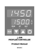
Product Manual
Open the catalog to page 1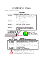
This manual comprises two volumes: OPERATING INSTRUCTIONS Monitoring the process and adjusting the setpoint Monitoring a running/held program Manual Control Using Guaranteed Soak Band Segment Event Status Setting up the controller parameters Setting up and using the communications link between the Profiler/Controller and your topic, refer to the index at the rear of this manual INSTALLATION & CONFIGURATION INSTRUCTIONS Panel-mounting and wiring-up the Profiler/Controller Selecting the required input/output type(s) Matching software to hardware fitted Selecting input range, control action, alarm...
Open the catalog to page 2
PRODUCT MANUAL OPERATING INSTRUCTIONS In normal operation, the operator must not remove the Profiler/Controller from its housing or have unrestricted access to the rear terminals, as this would provide potential contact with hazardous live parts. Installation and configuration must be undertaken only by technically-competent servicing personnel. This is covered in Volume I l .1 DISPLAY SEQUENCE - NO PROGRAM RUNNING 1 -1 1.3 PUTTING A PROGRAM IN HOLD 1 -2 1.4 RELEASING A PROGRAM FROM HOLD 1 -2 1.6 DISPLAY SEQUENCE - PROGRAM RUNNING 1 -3 1.7 RaPID CONTROL FEATURE 1 -4 1.9 ENGAGING BOTH PRE-TUNE...
Open the catalog to page 3
2 PROGRAM DEFINITION MODE - 2.3 DEFAULT VALUES AND ADJUSTMENT RANGES 2-9 2.4 EXIT FROM PROGRAM DEFINE MODE 2-9 3 CONTROLLER SET-UP MODE 3-1 3.2 EXIT FROM CONTROLLER SET-UP MODE 3-9 4.2 MODBUS FUNCTIONS SUPPORTED 4-1 4.5 PROFILER STATUS BYTE 4-11
Open the catalog to page 4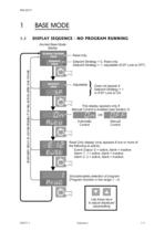
1.1 DISPLAY SEQUENCE - NO PROGRAM RUNNING Normal Base Mode Read only Setpoint Strategy = 0, Read only Setpoint Strategy = 1, adjustable (if SP Lock is OFF) Adjustable J Does not appear ¡f This display appears only if Manual Control is enabled (see Section 3) Read Only display (only appears if one or more of Event Output: E = active, blank = inactive Alarm 1:1= active, blank = inactive Alarm 2: 2 = active, blank = inactive Shows/enables selection of program (Program Number in the range 1 - 4)
Open the catalog to page 5
To start a program running: Select required Select required delay time 1.3 PUTTING A PROGRAM IN HOLD A program can be put in Hold (i.e. frozen) at any time whilst it is running. The program setpoint will stay at its value at the instant the program entered Hold until the program is released (see Subsection 1.4) or aborted (see Subsection 1.5). To put a program in hold, momentarily press the RUN key. The RUN indicator will flash whilst the program is in hold. 1.4 RELEASING A PROGRAM FROM HOLD To release a program currently in Hold, momentarily press the RUN key. The RUN indicator will then go...
Open the catalog to page 6
NOTE: When a program is aborted, the instrument returns to the Controller Setpoint value. If a program is successfully completed, the Controller Setpoint is automaticaly set to the final setpoint value of the program. If it is desired to restore the initial Controller Setpoint value after the program is completed, this value should be used as the program Final Setpoint value. 1.6 DISPLAY SEQUENCE - PROGRAM RUNNING Read only Active program setpoint value Read Only whilst Final setpoint value for current segment Time remaining in current segment jCycles remaining for current program; Omitted if...
Open the catalog to page 7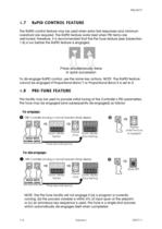
1.7 RaPID CONTROL FEATURE The RaPID control feature may be used when extra fast responses and minimum overshoot are required. The RaPID feature works best when PID terms are well-tuned; therefore, it is recommended that the Pre-Tune feature (see Subsection 1.8) is run before the RaPID feature is engaged. Press simultaneously twice To dis-engage RaPID control, use the same key actions. NOTE: The RaPID feature cannot be engaged if Proportional Band 1 or Proportional Band 2 is set to 0. This facility may be used to provide initial tuning of the Controllers PID parameters. Pre-Tune may be engaged...
Open the catalog to page 8
1.9 ENGAGING BOTH PRE-TUNE AND RaPID FEATURES The Pre-Tune and RaPID features can be engaged in one key action sequence: Press simultaneously twice Pre-Tune will operate first. When it is completed it will dis-engage itself and the RaPID feature will then operate automatically. 1.10 INDICATION OF PRE-TUNE AND RaPID STATUS The responses to the RaPID feature being engaged are: The responses to the RaPID feature being dis-engaged are: The responses to Pre-Tune being engaged are:
Open the catalog to page 9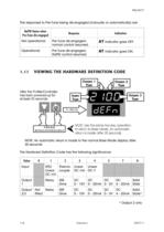
The responses to Pre-Tune being dis-engaged (manually or automatically) are: 1.11 VIEWING THE HARDWARE DEFINITION CODE NOTE: Use the same two-key operation to return to Base Mode. An automatic return is made after 30 seconds. NOTE: An automatic return is made to the normal Base Mode display after The Hardware Definition Code has the following significance:
Open the catalog to page 10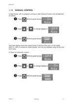
In Base Mode, with no program running or held, Manual Control may be selected front panel shows till front panel shows The lower display shows the output power in the form Pxxx (xxx is in the range 000% to 100% of maximum output power). This may be adjusted using the Up and Down keys. To return to automatic control: till front panel shows till front panel shows
Open the catalog to page 11
2 PROGRAM DEFINITION MODE - To enter Program Definition Mode: When display shows Program Define lock code NOTE: If the Program Define Mode lock code has been set to 0, pressing the Scroll key in Step 2 will give direct access to Program Define Mode; no entry of lock code is required. Upon entry into Program Define Mode, the first Segment Definition parameter for Segment 1 of Program 1 will be displayed.
Open the catalog to page 12
A program is created in two steps: 1. Define the segments of your program; the parameters used depend on what Program Mode has been configured - Rate Mode (see Subsection 2.2.2) or Time Mode (see Subsection 2.2.3). The segment definitions determine whether the selected segment is a Ramp Segment, a Dwell (soak) Segment or an End Segment. 2. Set the required Program Options (see Subsection 2.2.4). These (i) The number of cycles performed by the program, (li) The timebase to be used (hours/minutes or minutes/seconds) (IN) The width of the Guaranteed Soak Band (if enabled), (lv) The state of the...
Open the catalog to page 13
2.2.2 Defining Segments - Rate Mode -a\cea Qfli To make a 9*e ramp rate value final setpoint segment time Program Options Move to next segment NOTE: Ramp rate is in units/hour if Ramp rate is in units/minute if
Open the catalog to page 14All France Etuves catalogs and technical brochures
 XFL RANGE
4 Pages
 XFM RANGE
4 Pages
 XBR RANGE
2 Pages
 XL RANGE
4 Pages
 XAS
XAS2 Pages
 XXL Range
4 Pages
 XM
XM4 Pages
 XPP
XPP2 Pages
 Etuves XSV
2 Pages
 Four XKL
2 Pages
 Range XU universal oven
4 Pages
 WEST 6100+ Controller
157 Pages
 WEST 4400 Controller
38 Pages
 C3000 Controller
9 Pages
 Large Industrial Ovens XXL
2 Pages
 Industrial Ovens XL
2 Pages
 Vacuum ovens XF
2 Pages
 High temperature ovens XHT
2 Pages
 Laboratory Furnaces XKL
2 Pages
 Universal Ovens XU
2 Pages


Archived catalogs
 Laboratory furnace
2 Pages
 High temperature oven
2 Pages
 Cooled incubator
2 Pages
 Fan circulated incubator
2 Pages
 Incubator
2 Pages
 Industrial oven
2 Pages
 Vacuum oven
2 Pages
 Glassware drying oven
2 Pages
 Laboratory oven
2 Pages