
Catalog excerpts
PREFACE This manual is intended for use in support of day-to-day operation of 1 the 4 -DIN Setpoint Programmer. For information on installation, commissioning, configuration etc., refer to the associated Site Manual (see below). Associated Documents Title 1 4 -DIN Setpoint Programmer Site Manual Part No. 59xxxx In normal operation, the operator must not remove the Setpoint Programmer from its housing or have unrestricted access to the rear terminals, as this would provide potential contact with hazardous live parts. Installation and configuration must be undertaken only by personnel who are...
Open the catalog to page 2
59215 Contents 1 INTRODUCING THE SETPOINT PROGRAMMER 1-1 2 FRONT PANEL CONTROLS, INDICATORS & DISPLAYS 2-1 2.1 2.2 2.3 2.4 2.5 3 3.1 3.2 3.3 3.4 3.5 3.6 3.7 3.8 CONTROLS . . . . . . . . . . . . . . . . . . . . . . . . . INDICATORS . . . . . . . . . . . . . . . . . . . . . . . . DISPLAYS . . . . . . . . . . . . . . . . . . . . . . . . . . ALARM STATUS INDICATION . . . . . . . . . . . . . . . VIEWING PROGRAM AND CONTROLLER PARAMETERS . . . . . . . . . . . . . . . . . . . . . . . . . . . . . . . . . . . . . . . . . . . . . PROGRAMS SELECTING AND RUNNING A PROGRAM. . . . . . . . . CHANGING THE...
Open the catalog to page 3
59215 9 9.1 9.2 9.3 9.4 DEFINING THE CONTROLLER PARAMETERS (CONTROLLER DEFINE MODE) 9-1 CONTROLLER PARAMETERS . . . . . . . . . . . . . . . . . . . . . . . . 9-2 BASE MODE DISPLAYS . . . . . . . . . . . . . . . . . . . . . . . . . . . 9-10 LOOP ALARM AND LOOP ALARM TIME . . . . . . . . . . . . . . . . . . 9-10 EXITING CONTROLLER DEFINE MODE . . . . . . . . . . . . . . . . . . 9-11 Alphabetic Index (iv) 59215-FM
Open the catalog to page 4
59215 1 INTRODUCING THE SETPOINT PROGRAMMER The Setpoint Programmer is a powerful, easy-to-use 14-DIN instrument with full PID control capability (complete with Self-Tune/Pre-Tune facilities). Its standard features are: * Up to eight programs of up to 16 free-format (e.g. dwell, ramp, join or end) segments each. * Facility to join programs to one another in any sequence (maximum program length 121 segments). * User can change currently-running program segment. * * Delayed Start of Program facility. * Universal input - thermocouple, RTD (Pt100) or DC linear - user- selectable). * Universal...
Open the catalog to page 5
59215 The Setpoint Programmer has four operating modes: Base Mode: Day-to-day PID control operations with no program running. In this mode, a program may be selected to run. Program Run Mode: A selected program is running, held or waiting for a pre-defined delay before starting. In this mode, the operator can view status and program information. Program Define Mode 1: Used to view/create/edit programs. This mode is entered either from Base Mode (selected program may be edited/created) or from Program Run Mode (currently-running program may be edited). Controller Define Mode 2: Used to...
Open the catalog to page 6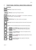
59215 2 2.1 FRONT PANEL CONTROLS, INDICATORS & DISPLAYS CONTROLS MODE key: Changes mode of instrument. PROG key: Cycles through Program Numbers. Scroll key: Displays the next parameter in the sequence (indicated by Message Display - see Subsection 2.3). RUN/HOLD key: Runs, holds or aborts current program. Down key: Decrements displayed parameter value/cycles through options. Up key: Increments displayed parameter value/cycles through options. Up and MODE keys: Selects/de-selects Self-Tune or Pre-Tune (when Message Display shows appropriate message. Up and PROG keys: Jumps to next segment,...
Open the catalog to page 7
59215 2.2 INDICATORS Control Status Indicators AT ON when Self-Tune is active; flashes when Pre-Tune is active. ALM Flashes when any alarm is active. OP1 ON when primary control output is active. OP2 ON when secondary control output (if fitted) is active. MAN ON when Manual Control is selected. Run Status Indicators RUN ON - Program running or (if HLD ON also) held Flashing - Program in Delayed state HLD ON - Program held Flashing - Program in Auto-Hold x60 OFF - timebase = hours/minutes Event Indicators Each indicates the status (active or inactive) of a user-defined event (OFF = inactive,...
Open the catalog to page 8
UPPER DISPLAY Process variable value MESSAGE DISPLAY PROGRAM NUMBER selected program LOWER DISPLAY Setpoint value or value/setting of parameter being viewed/edited SEGMENT NUMBER Number of current segment CURRENT RAMP STATE § (Both flashing) - In Manual control while program is running Appears only if Alarm 1 is active ■ Appears only if Alarm 2 is active ■ Appears only if Loop Alarm is active NOTE: If no alarm is active, this display is not available
Open the catalog to page 9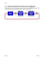
59215 2.5 VIEWING PROGRAM AND CONTROLLER PARAMETERS In Base Mode (i.e. with no program currently running or held), the MODE key gives “view only” access to Program Define Mode and Controller Define Mode: Page 2-4 59215-2
Open the catalog to page 10
59215 3 3.1 PROGRAMS SELECTING AND RUNNING A PROGRAM When no program is running, the Setpoint Programmer is in Base Mode and the RUN and HLD indicators are OFF. In this mode, select a program as follows: 1. Hold down the PROG key until the required program number is displayed. 2. Press the Run/Hold key once to start the program. The RUN indicator will then go ON; the Setpoint Programmer is now in Program Run Mode. 3.2 CHANGING THE PROGRAM TIMEBASE Whilst a program is running, the normal timebase is hours/minutes. To change to a timebase of minutes/seconds (i.e. select the x60 facility),...
Open the catalog to page 11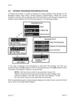
Pre-Tune Status (OFFor On in lower display) Self-Tune Status (OFFor On in lower display) Alarm Status Manual Cortrol Delay Time Remaining Segment Time Remaining Auto-H@Id Tim®
Open the catalog to page 12
59215 3.6 ABORTING A PROGRAM The operator may abort (i.e. terminate) the current program by holding down the Run/Hold key for more than five seconds. When the program is aborted, a return is made to the Base Mode and the Message Display will show: This message will be removed by the next keypress. 3.7 “END OF PROGRAM” INDICATION When the program has reached its End Marker, the Message Display shows: and a return is made to Base Mode. 3.8 VIEWING PROGRAM AND CONTROLLER PARAMETERS In Program Run Mode (i.e. with a program currently running or held), the MODE key gives “view only” access to...
Open the catalog to page 13All France Etuves catalogs and technical brochures
-
XFL RANGE
4 Pages
-
XFM RANGE
4 Pages
-
XBR RANGE
2 Pages
-
XL RANGE
4 Pages
-
XAS
2 Pages
-
XXL Range
4 Pages
-
XM
4 Pages
-
XPP
2 Pages
-
Etuves XSV
2 Pages
-
Four XKL
2 Pages
-
Range XU universal oven
4 Pages
-
WEST W6400 Controller
82 Pages
-
WEST 6100+ Controller
157 Pages
-
C3000 Controller
9 Pages
-
Large Industrial Ovens XXL
2 Pages
-
Industrial Ovens XL
2 Pages
-
Vacuum ovens XF
2 Pages
-
High temperature ovens XHT
2 Pages
-
Laboratory Furnaces XKL
2 Pages
-
Universal Ovens XU
2 Pages
-
Special ovens for composites
1 Pages
Archived catalogs
-
Laboratory furnace
2 Pages
-
High temperature oven
2 Pages
-
Cooled incubator
2 Pages
-
Fan circulated incubator
2 Pages
-
Incubator
2 Pages
-
Industrial oven
2 Pages
-
Vacuum oven
2 Pages
-
Glassware drying oven
2 Pages
-
Laboratory oven
2 Pages


