- Catalogs
- Fracsun Inc
- ARES Modbus Documentation
ARES Modbus Documentation
1 /15Pages

ARES Modbus Documentation
1 /15Pages
Catalog excerpts

Fracsun Modbus Documentation July 1, 2022 1.0 Introduction This document is intended to provide the necessary information to connect the Fracsun soiling solution to an onsite SCADA system or datalogger via Modbus RS-485 protocol. 1.1 ARES and Wash Extension The Fracsun soiling monitoring solution often encompasses two separate devices: ARES and the Wash Extension. Both devices are configurable as Modbus Slaves to transfer data into the onsite SCADA system via a Modbus RTU RS-485 connection. 1.2 ARES Cellular-only and Modbus-only modes In the default state, ARES is an IoT cellular-enabled device that automatically connects to the nearest cellular base station and outputs data to the Fracsun cloud. The customer can view the data on Fracsun Dashboard. The Fracsun Cloud also performs additional data processing. For example, the daily soiling loss and insolation values are calculated (filtered and weighted) as a cloud process. ARES can also operate in Modbus-only mode for wired connections to dataloggers and SCADA systems, which is most likely the preferred connection method for customers reading this document. The cellular modem is turned off in this mode, which stops the flow of data to the Fracsun Cloud. This also means that the daily calculated data (daily soiling loss, insolation, and Wash Analysis) can no longer occur in Modbus-only mode because the Fracsun cloud process cannot run without the data. In either mode, Fracsun has options to transfer soiling sensor data between the Fracsun Cloud and the data acquisition system (DAS). Please reach out for more information or read our API Documentation.
Open the catalog to page 1
2.0 Modbus Information 2.1 Modbus commands These commands are all according to the Modbus RTU protocols described in: ‘Modbus® over serial line V1.02’ and ‘MODBUS application protocol V1.1b’ available from the Modbus® organization (www.modbus.org). These commands can be tested using software tools, such as ‘Modbus Poll’ from www.modbustools.com. The following commands are implemented: Function Read Holding Register (Single or Multiple) Write Single Register Write Multiple Registers 2.2 RS-485 Configurations The following slave addresses, baud rates and frame configurations are available on both...
Open the catalog to page 2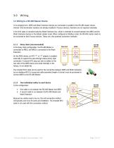
3.0 Wiring 3.1 Wiring to a RS-485 Master Device In its simplest form, ARES and Wash Extension devices are connected in parallel to the RS-485 master device. Internal 120Ω termination resistors are already installed in Fracsun devices, therefore are not required externally. A 3m M12 cable is included inside the Wash Extension box, which is intended to connect between the ARES and the Wash Extension devices in the default cellular mode. When configured in Modbus mode, the RS-485 master needs to be connected to both Fracsun devices. These are a few potential connection methods: Daisy chain (recommended)...
Open the catalog to page 3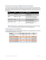
3.2 External power requirements in Modbus-only and Cellular-only modes In the default Cellular-only mode, ARES and Wash Extension devices are solar-powered and do not require external power. However, in Modbus-only mode, just the ARES device requires external power. The Wash Extension can even provide power to ARES through the M12 connection. The table below summarizes the external power requirements for each device. Device Additional Notes Solar-powered when outside, but can also use voltage supply. 12V from Wash Extension can power ARES, but can also use voltage supply. Wash Extension Solar-powered...
Open the catalog to page 4
3.5 ARES M12 connection diagram 3.5.1 ARES devices built 2021 and later For installations utilizing Modbus-only mode (an external Modbus RTU connection) or Modbus + Cellular mode, use the M12 pinout diagram below to connect ARES to the RS-485 Master. 1 5 3 2 4 Wire Brown Gray Blue White Black Shield Connection description Modbus RS-485 B+ / B / B’ Modbus RS-485 A- / A / A’ Modbus common / ground * Power Input +11 to +30Vdc ** Power common / ground Housing * * Not a required connection. ** Absolute max power input voltage is 30 Vdc. Do not exceed. Pin assignment for M12 socket (male) M12 socket...
Open the catalog to page 5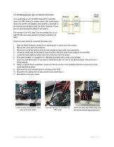
3.7 Enabling power pins on Wash Extension If you would like to use the Wash Extension to externally power the ARES device (or another device with similar power draw), the positive and negative wires must be connected on the internal terminal block inside the Wash Extension. These pins are disconnected by default in the factory. The included 5-pin M12 cable (3m) has enough pins to run both RS-485 and power between the Wash Extension and ARES. Follow the steps below to reconnect the power pins. 1. 2. 3. 4. 5. 6. 7. Open the Wash Extension enclosure by removing the 4 screws from the corners. Remove...
Open the catalog to page 6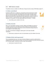
4.0 ARES device modes Three different modes are available in the ARES device. Change the mode by writing to ARES Modbus register 44. 4.1 Cellular mode (default) By default, the ARES device is configured as a self-powered and self-commissioning IoT cellular device. The device turns on, takes a few measurements, sends the data to the cloud, and then goes into a low-power sleep state to reduce battery power consumption. Any Modbus polling attempts during measurement or sleep states will almost always result in a timeout or missed poll. There is a very short ~3 second window in which a single poll...
Open the catalog to page 7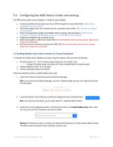
5.0 Configuring the ARES device modes and settings The ARES device modes can be changed in a variety of ways including: • • • • • • A remote command can be issued over-the-air (OTA) through the Fracsun Web Portal. ARES must be connected to cloud via cellular. The Fracsun support team can remotely issue the command on your behalf. ARES must be connected to cloud via cellular. Write to the appropriate registers (see Modbus Mode and Apply Code parameters). ARES must be connected to a Modbus RS-485 Master device (or a PC with Modbus Poll software). Shipped preconfigured with a particular mode. Button...
Open the catalog to page 8
5.2 Enabling Modbus-only mode via RS-485 To change from Cellular-only to Modbus-only mode using this method, verify you have the following: • • • • • DC power source (11 – 30 V) or device placed in direct sun for at least 1 hour M12 5pin A-coded female to loose-end cable Antenna fastened in with LTE or 3G signal RS-485 to USB Adapter Computer with Modbus Poll or similar software Follow the instructions below to enable Modbus-only mode: 1. 2. 3. 4. Connect the M12 5pin female to loose-end cable between the ARES device and RS-485-to-USB adapter. Power ARES using the DC power source (over the M12...
Open the catalog to page 9All Fracsun Inc catalogs and technical brochures
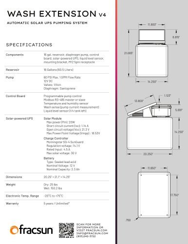 WASH EXTENSION V4
1 Page
 PV Soiling Monitoring Solution
21 Pages
 CLEO
CLEO2 Pages
 ARES Installation Manual
15 Pages